Adaptive beamformer, sidelobe canceller, handsfree speech communication device

A technology of adaptive beam and sidelobe suppressor, applied in the field of adaptive beamforming or sidelobe suppression, tracking equipment, and consumer devices, can solve problems such as difficult systems, returning to the optimal state, and easy separation

Active Publication Date: 2007-04-11
MEDIATEK INC
View PDF2 Cites 14 Cited by
  • Summary
  • Abstract
  • Description
  • Claims
  • Application Information

AI Technical Summary

Problems solved by technology

In particular, a sidelobe suppressor that adaptively adjusts its filter using the clean signal obtained after many processing steps, although it can obtain a good estimate of the optimal fi

Method used


Image

  • Adaptive beamformer, sidelobe canceller, handsfree speech communication device
  • Adaptive beamformer, sidelobe canceller, handsfree speech communication device
  • Adaptive beamformer, sidelobe canceller, handsfree speech communication device

Examples


Embodiment Construction

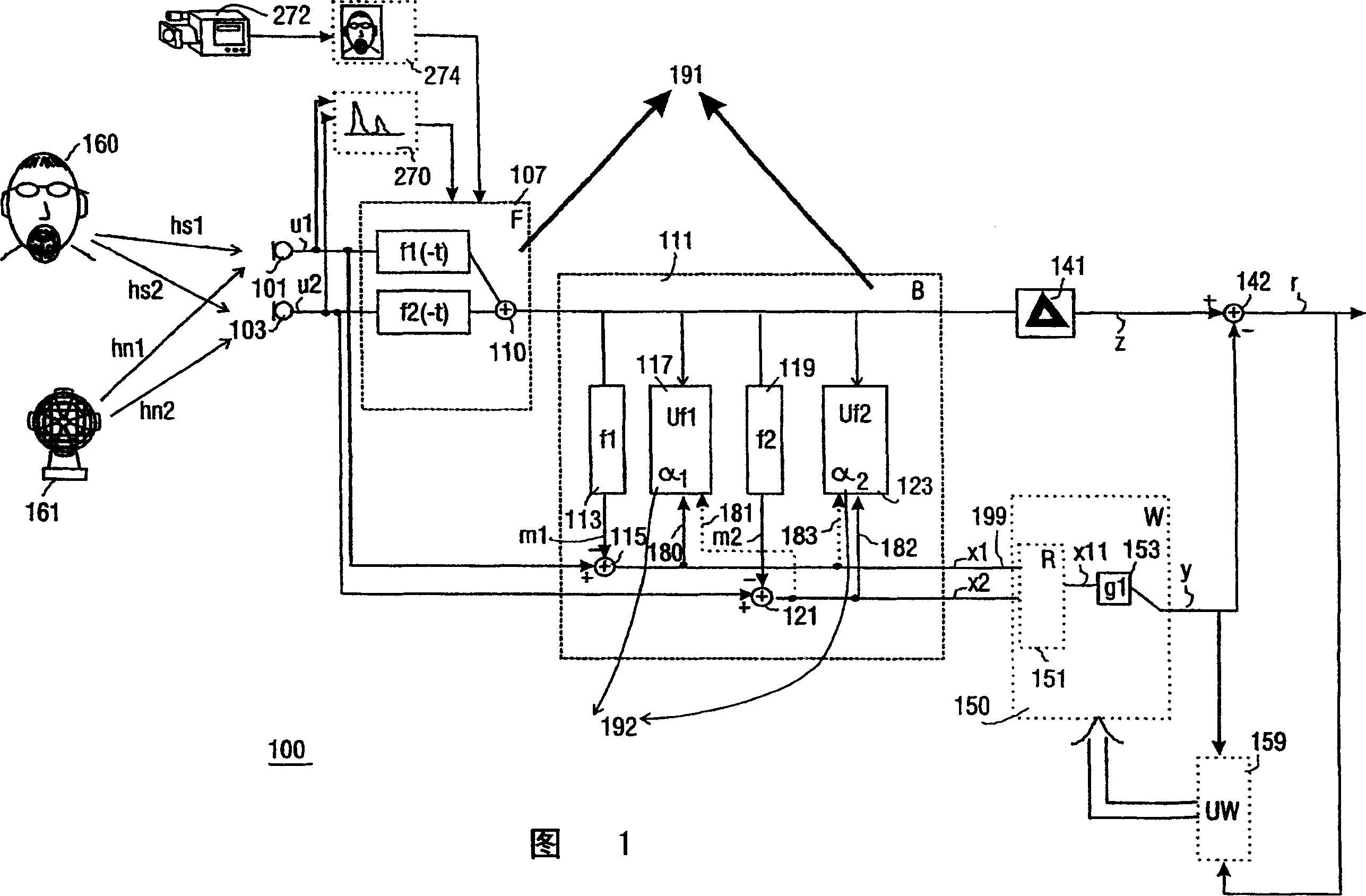
[0049] In FIG. 1 , from a desired sound source 160 and possibly also from one or more undesired noise sources 161 (noise should not be understood as only random signals such as electronic thermal noise, but any undesired / interfering audio signal) Sound, which propagates to an array of at least two microphones 101,103. The signals u1, u2 output by these microphones are filtered by a first set of filters f1(-t), f2(-t) of a respective beamformer 107, the coefficients of which filter - typically one coefficient per frequency band - Able to adapt adaptively to spatially varying conditions, such as a moving desired sound source 160 . The resulting signals output by the respective filters are added by an adder 110 to generate a first audio signal z. Ideally, the filter represents the reverse path of the desired signal towards the particular microphone, so filtering the first microphone signal u1 with the first filter f1(-t) ideally obtains exactly the desired sound. Therefore, if ...


PUM


Abstract

The adaptive beamformer unit (191) comprises: a filtered sum beamformer (107) arranged to process input audio signals (u l, u2) from an array of respective microphones (101, 103), and arranged to yield as an output a first audio signal (z) predominantly corresponding to sound from a desired audio source (160) by filtering with a first adaptive filter (fl (-t)) a first one of the input audio signals (u l) and with a second adaptive filter (f2(-t)) a second one of the input audio signals (u2), the coefficients of the first filter (fl(-t)) and the second filter (f2(-t)) being adaptable with a first step size (al) and a second step size ((x2) respectively; noise measure derivation means (111) arranged to derive from the input audio signals (ul, u2) a first noise measure (xl) and a second noise measure (x2); and an updating unit (192) arranged to determine the first and second step size (al, (x2) with an equation comprising in a denominator the first noise measure (xl) for the first step size (al), respectively the second noise measure (x2) for the second step size (a2). This makes the beamformer relatively robust against the influence of correlated audio interference. The beamformer may also be incorporated in a sidelobe canceller topology yielding a more noise cleaned desired sound estimate, which can be used in a related, more advanced adaptive filter (fl (-t), f2(-t)) updating. Such a beamformer is typically useful for application in handsfree speech communication systems.

Description

technical field [0001] The present invention relates to an adaptive beamformer unit and a sidelobe suppressor comprising the adaptive beamformer. [0002] The invention also relates to an automatic voice communication system comprising the adaptive beamformer or sidelobe suppressor, a portable voice communication device, a sound control unit and a tracking device for tracking audio producing objects. [0003] The invention also relates to a consumer device comprising the sound control unit. [0004] The invention also relates to a method of adaptive beamforming or sidelobe suppression and a computer program product comprising the code of the method. Background technique [0005] One embodiment of a sidelobe suppressor and included beamformer as described in the first paragraph can be found in the publication "C. Fancourt and L. Parra: The generalized sidelobe decorator. Proceedings of the IEEE Workshop on applications of signal processing to audio andacoustics 2001." learn...

Claims


Application Information

Patent Timeline
IPC IPC(8): G10K11/34G10L21/0208G10L21/0232
CPCG10K11/341G10K11/00G10K11/34
Inventor B·E·萨罗克哈C·P·詹塞
Owner MEDIATEK INC
Why Eureka
Try Eureka