High-pressure sodium lamp

A high-pressure sodium lamp and very high-frequency technology, applied in the field of lighting systems, can solve problems such as inability to realize new opportunities, and achieve good maintenance effects

Inactive Publication Date: 2007-04-11
KONINKLIJKE PHILIPS ELECTRONICS NV
View PDF0 Cites 2 Cited by
  • Summary
  • Abstract
  • Description
  • Claims
  • Application Information

AI Technical Summary

Problems solved by technology

However, these new opportunities cannot be achieved with currently known lamps, whether these lamps are operated by conventional induction ballasts, or in combination with all electronic VHF ballasts. chance, which is considered a shortcoming of the known system

Method used


Image

  • High-pressure sodium lamp
  • High-pressure sodium lamp
  • High-pressure sodium lamp

Examples


Embodiment Construction

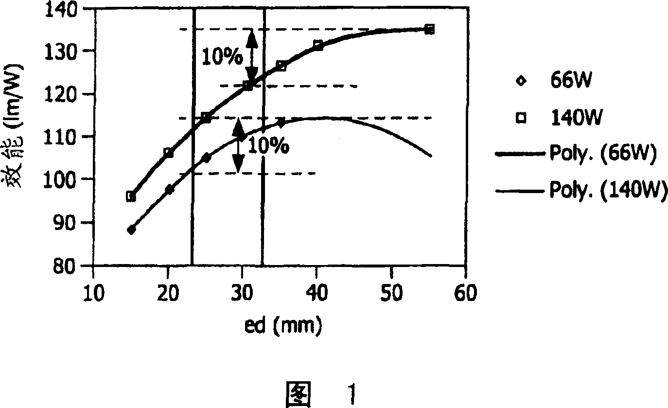
[0037] With electronic ballasts, the lamp voltage can be freely selected, as opposed to working with conventional CuFe ballasts. A shorter light source (shorter electrode distance) gives the possibility to more efficiently bundle the light emitted from the illuminant, resulting in a higher luminous flux on the illuminated surface.

[0038] A consequence of the shorter electrode distance is a lower lamp voltage and thus a higher lamp current. Higher lamp currents lead to higher power losses in the ballast, which in turn leads to lower lamp efficacy (especially if mercury-rich amalgam is used to limit voltage drop). Optimum system efficacy is thus a compromise between lamp, ballast and luminaire efficacy.

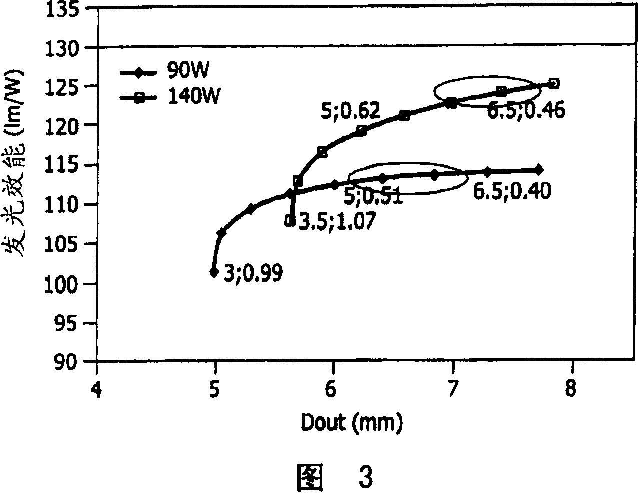
[0039] Therefore lower electrode distances (and thus higher lamp currents) combined with higher ballast efficiencies (>90%) are only possible when VHF ballasts are used. Losses in VHF ballasts are significantly lower than in conventional ballasts: 6 and 12 W at Vla=55 V for...


PUM


Abstract

The invention is related to high pressure sodium lamp having a nominal power Pla. The lamp, which is designed to be operated at a very high frequency (VHF), has a discharge tube with a ceramic wall and an internal vessel diameter Dint, which encloses a discharge space in which a pair of electrodes at a mutual electrode distance ed and a filling of Na-amalgam with a sodium mol fraction (smf). According to the invention the discharge tube has a ratio ed / Dint of at most 7, preferably between about 5.5 and 4.0.

Description

technical field [0001] The invention relates to a high-pressure sodium (HPS) lamp suitable for operation at very high frequencies (VHF) with the highest possible luminous efficacy. In operation, the lamp is driven by an all-electronic driver (also known as an all-electronic ballast). It is best to take frequencies in the region where acoustic resonances will occur in the lamp. [0002] The invention also relates to a lighting system comprising a fully electronic VHF driver for operating said high pressure sodium (HPS) lamp. [0003] Known PHS lamps are equipped with a discharge chamber or discharge vessel with ceramic walls. In this context, ceramic refers to walls made of crystalline metal oxides like single crystal sapphire or high density sintered polycrystalline metal oxides such as polycrystalline alumina (PCA) and YAG or metals like AlN Nitride walls. These materials are well known in the art for their ability to be prepared with good translucent properties. [0004...

Claims


Application Information

Patent Timeline
Patent Type & Authority Applications(China)
IPC IPC(8): H01J61/82H05B41/288
CPCH01J61/825
Inventor C·B·A·斯图尔J·詹扎克H·M·L·E·赫雷曼斯J·C·M·亨德里克西
Owner KONINKLIJKE PHILIPS ELECTRONICS NV
Why Eureka
Try Eureka