Braking device for garden tools

A brake device and garden tool technology, which is applied in the direction of brake types, drum brakes, couplings and brakes, etc., can solve the problems of high parts processing requirements, large number of parts, and high production costs, and achieve good results. Braking function, reduced production cost, simple structure

Inactive Publication Date: 2007-04-18
SKYBEST ELECTRIC APPLIANCE SUZHOU CO LTD
View PDF0 Cites 14 Cited by
  • Summary
  • Abstract
  • Description
  • Claims
  • Application Information

AI Technical Summary

Problems solved by technology

Some mechanical braking devices are used, but the structures of the currently disclosed mechanical braking devices are relatively complex, the number of parts required is large, and the processing requirements for the parts are also high, resulting in high production costs

Method used


Image

  • Braking device for garden tools
  • Braking device for garden tools
  • Braking device for garden tools

Examples


Embodiment 1

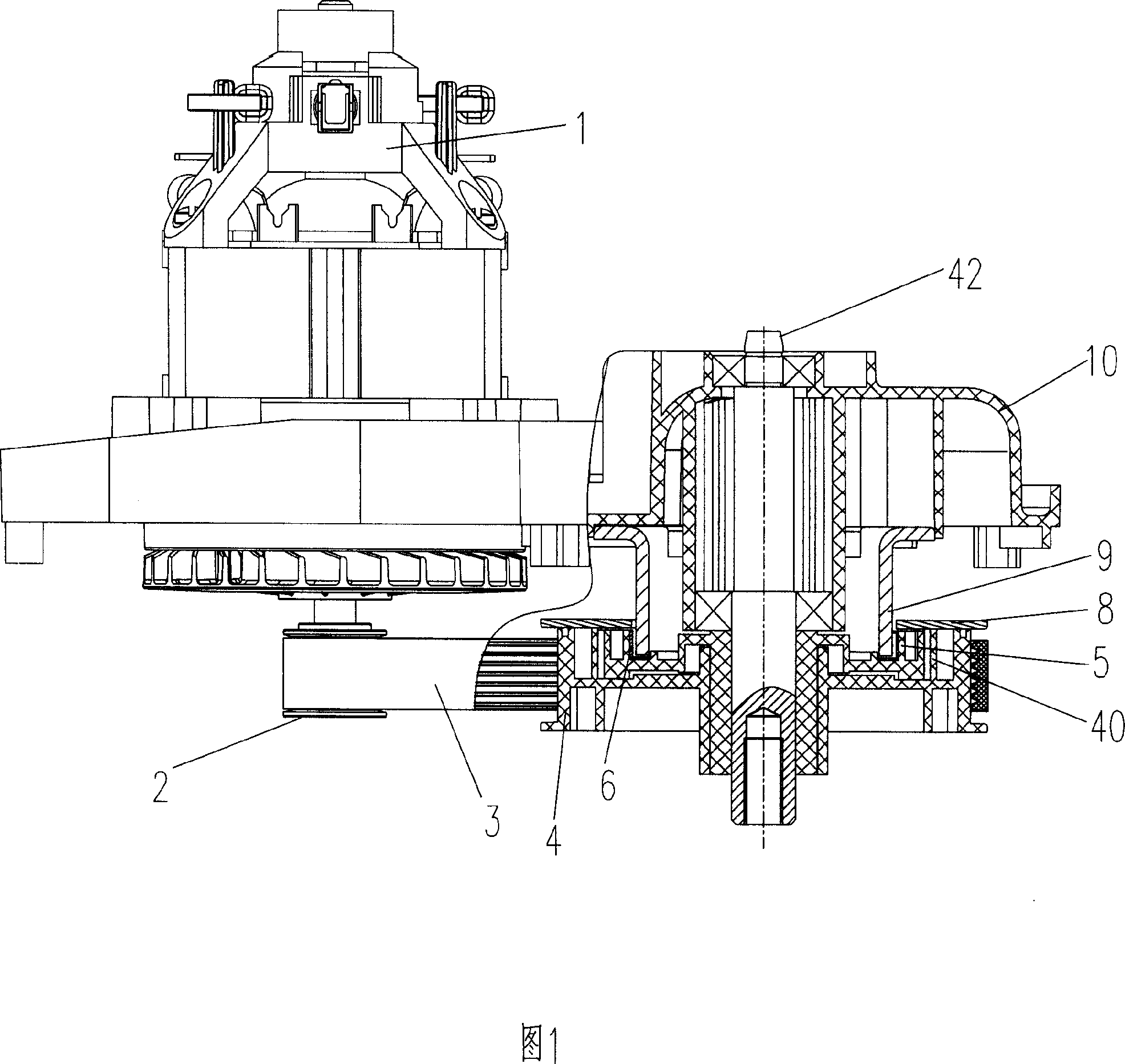
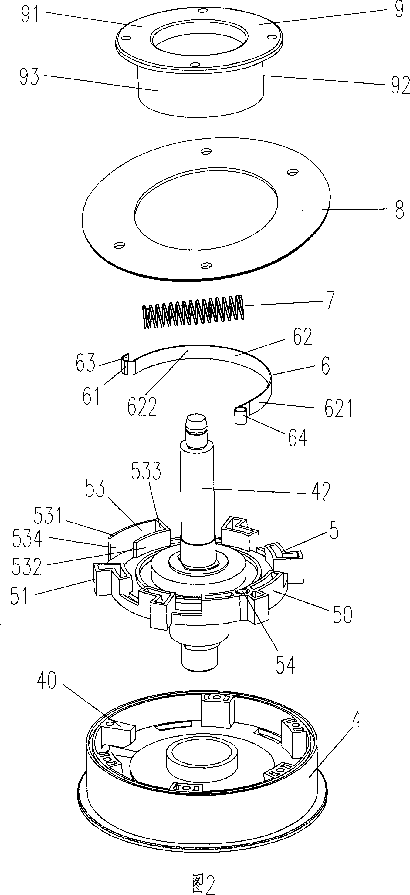
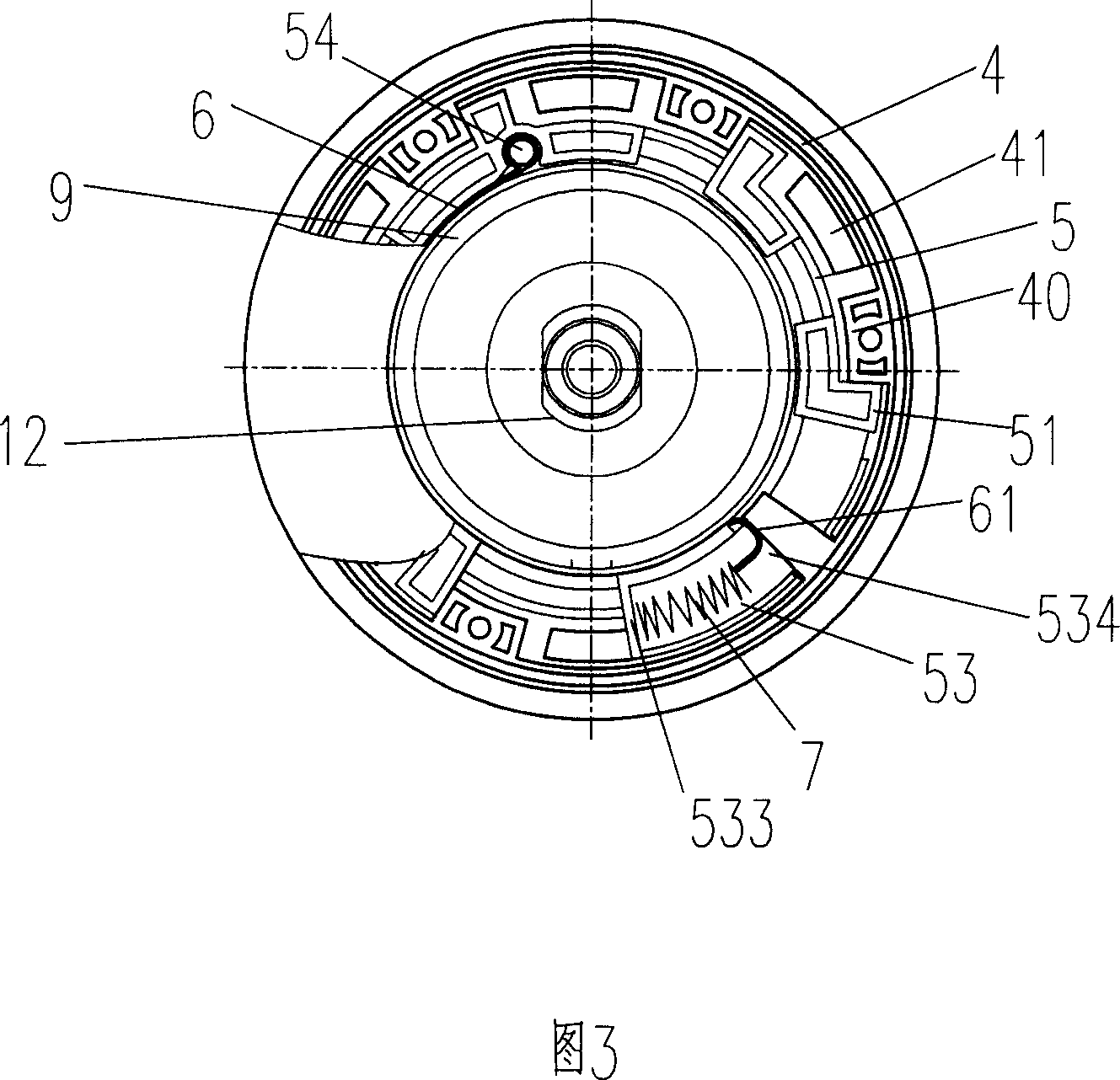
[0015] Its structure of present embodiment is shown in Fig. 1 to Fig. 3, and garden tool of the present invention uses braking device, and wherein garden tool comprises motor 1, driving wheel 2, belt 3 and the working shaft 42 that is used to install cutter, and braking device consists of It consists of a working wheel assembly that rotates around the working shaft 42 and a braking element. The working wheel assembly is composed of an inner wheel 5 fixedly connected to the working shaft 42 and an outer wheel 4 sleeved outside the inner wheel 5 , and the belt 3 is wound on the outer wall of the outer wheel 4 . Wherein, a plurality of protrusions 40 are arranged on the inner wall of the outer wheel 4, and the protrusions 40 extend from the inner wall to the center. On the outer wall surface 50 of the inner wheel 5 , a plurality of protrusions 51 corresponding to the protrusions 40 of the outer wheel 4 are provided, and the protrusions 51 protrude outward from the outer wall surf...

Embodiment 2

[0019] Referring to Figures 4 to 6, in this embodiment, the outer wheel 4' includes an outer wall 41' and an inner wall 45', wherein a plurality of protrusions 40' are arranged on the inner side of the outer wall 41', and the protrusions 40' The inner side extends toward the center. And the outer wall surface 50' of the inner wheel 5' is provided with some protrusions 51' corresponding to the projections 40' of the outer wheel 4', and the protrusions 51' protrude outwards from the outer wall surface 50'. When the outer wheel 4' is assembled with the inner wheel 5' and the working wheel assembly rotates normally, the protrusion 40' of each outer wheel 4' abuts against the protrusion 51' of each inner wheel 5', thereby driving the inner wheel 5 'rotate around the working axis 42'.

[0020] The braking element is composed of a first braking element 6', a second braking element 9' and an elastic element 7'. A receiving groove 43' is provided between the outer wall 41' and the in...


PUM


Abstract

A brake mechanism for the garden's tool with a working axle for installing cutting tool to it is composed of a working wheel module consisting of an internal wheel fixed to said working axle and an external wheel surrounding the internal wheel, the first and the second braking elements which are in contact with each other when they are in barking state, and an elastic element in said internal or external wheel.

Description

Technical field [0001] The invention relates to a braking device for a garden tool, in particular to a circumferential braking device for a garden tool. Background technique [0002] After the power source of the garden tool is cut off, its working axis will not stop soon due to inertia. But there are some devices with special requirements, after the power source is cut off, the rotary member installed on the working shaft can stop rotating quickly, such as a lawn mower. The rotating part installed on the working shaft on the lawn mower is the blade, and the working shaft and the main shaft of the motor are driven by a belt. For safety reasons, the blade is required to stop rotating quickly within a certain period of time after the power of the motor is cut off. At present, the above-mentioned garden tools all adopt some devices to help realize fast braking. Among them, electronic braking devices are used, but once the electronic components fail, the phenomenon of "seizure...

Claims


Application Information

Patent Timeline
Patent Type & Authority Applications(China)
IPC IPC(8): A01D69/10
CPCA01D34/828A01D34/6812F16D67/02F16D49/00
Inventor 桑树华魏娟
Owner SKYBEST ELECTRIC APPLIANCE SUZHOU CO LTD
Why Eureka
Try Eureka