Ultraviolet illuminating apparatus

A technology of irradiation device and ultraviolet rays, which is applied in the direction of lighting device, cooling/heating device of lighting device, lighting and heating equipment, etc., which can solve the problem of poor perception and achieve the effect of miniaturization

Active Publication Date: 2007-04-18
USHIO DENKI KK
View PDF2 Cites 19 Cited by
  • Summary
  • Abstract
  • Description
  • Claims
  • Application Information

AI Technical Summary

Problems solved by technology

It can also be seen from the same figure that the device as a whole is made large and the appearance is not good

Method used


Image

  • Ultraviolet illuminating apparatus
  • Ultraviolet illuminating apparatus
  • Ultraviolet illuminating apparatus

Examples


Embodiment Construction

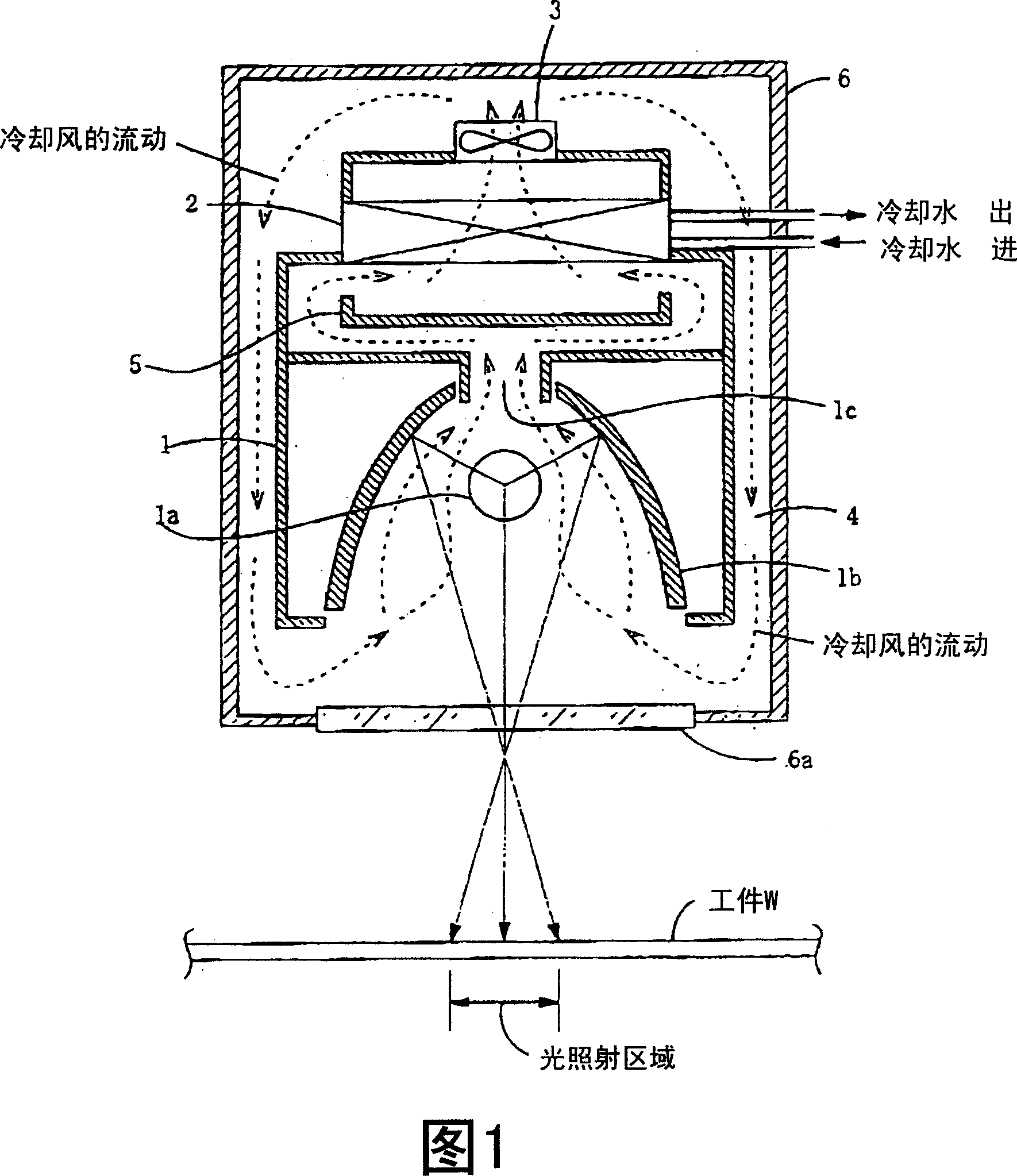
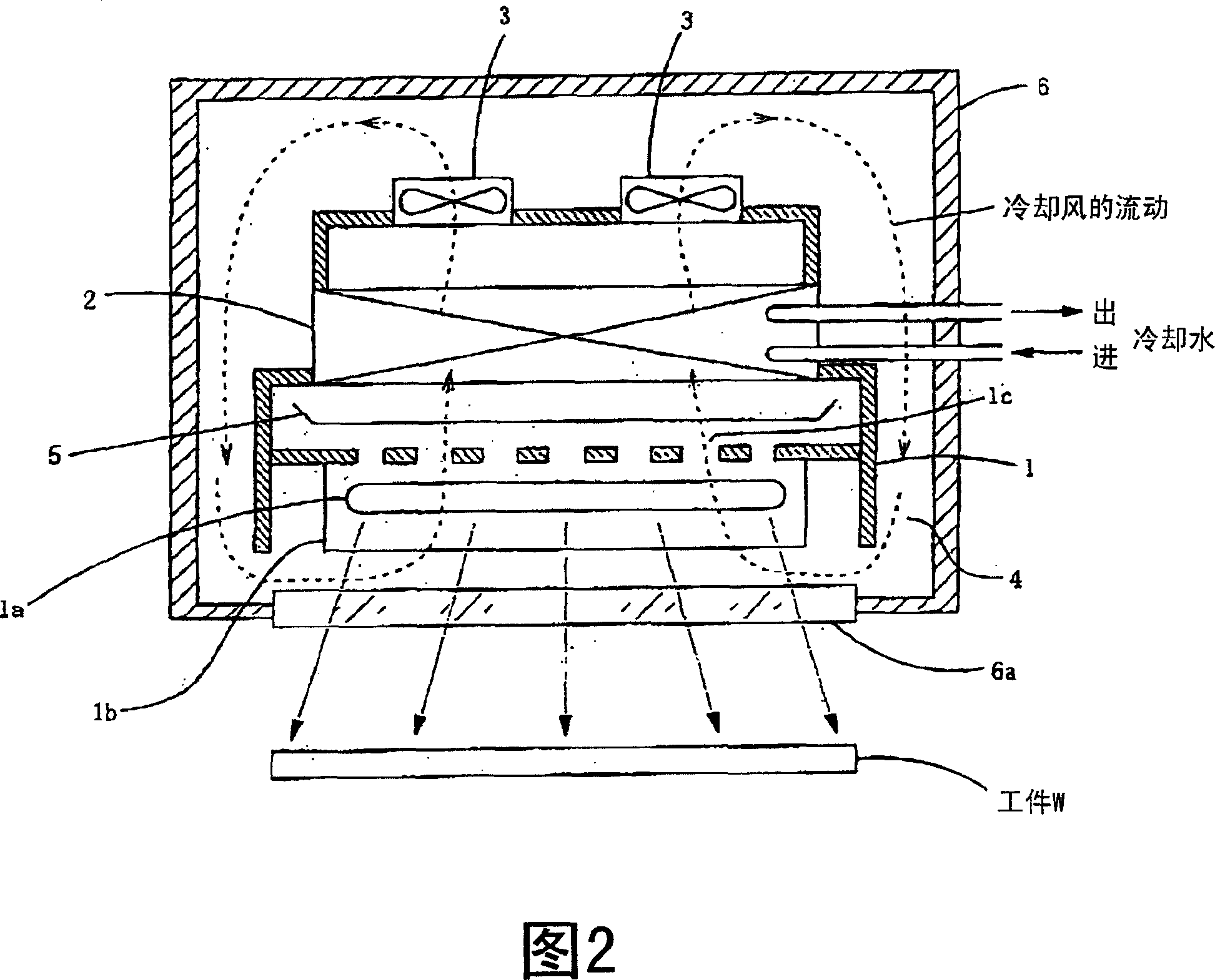
[0055] 1 and 2 are diagrams showing the configuration of an ultraviolet irradiation device according to a first embodiment of the present invention. Fig. 1 is a sectional view showing a direction perpendicular to the longitudinal direction of the lamp; Fig. 2 is a sectional view showing a direction along the longitudinal direction of the lamp. 1 and 2 both omit to show the power supply unit.

[0056] As shown in Figures 1 and 2, the ultraviolet irradiation device of this embodiment is provided with: a light source unit 1 having a lamp 1a and a reflector 1b reflecting ultraviolet rays from the lamp 1a, and a refrigerator 2 ( Radiator), and a casing 6 having a transmission window 6a that transmits ultraviolet rays emitted from the light source unit 1 in a three-unit manner surrounding a blower 3 (blower) that generates cooling air. A gap is provided between the housing 6 and the light source unit 1 to form a ventilation path.

[0057] The lamp 1 a provided in the light source ...


PUM


Abstract

The present invention provides a light irradiation device that circulates cooling air and cools a light source part. The heated portion of the cooling air due to temperature rise is not exposed to the outside, and the size of the device is not increased, and the space occupied by the device can be reduced. UV irradiation unit for the floor area. Inside the housing (6) with a light transmission window are: a light source unit (1) with a lamp (1a) and a reflector (1b); a blower (3); and a refrigerator (2) for cooling the cooling air. The cooling air sent from the blower (3) is introduced into the light source unit (1) through the ventilation passage formed between the light source unit (1) and the housing (6) to cool the lamp (1a) and The reflection mirror (1b) is introduced into the refrigerator (2) through the cooling air ventilation hole (1c) provided in the reflection mirror (1b). The cooling air cooled by the refrigerator (2) is returned to the blower (3).

Description

technical field [0001] The present invention relates to an ultraviolet irradiation device that circulates cooling air for cooling lamps and irradiates ultraviolet rays. Background technique [0002] UV rays emitted from discharge lamps such as high-pressure mercury lamps or metal halide lamps are irradiated on adhesives, paints, inks, photoresists, etc. that are sensitive to ultraviolet rays to harden or dry them, or vice versa. Various treatments such as melting or softening. [0003] In order to prevent heating during lighting, the lamp is cooled by cooling air. Recently, a device for circulating cooling air in order to reduce consumption of cooling air has been proposed. For example, devices described in Patent Document 1 and Patent Document 2 are known. [0004] In FIG. 1 of Patent Document 1, it is disclosed that the cooling air that cools the light source lamp 11 or the reflector 12, etc., is supplied to the circulating air path through the exhaust blower 22 after the...

Claims


Application Information

Patent Timeline
Patent Type & Authority Applications(China)
IPC IPC(8): F21V29/00F24F7/06F21Y101/00
CPCF24F3/056F24F13/078F24F2221/02
Inventor 矢羽田强
Owner USHIO DENKI KK
Why Eureka
Try Eureka