Semi-disposable optoelectronic rapid diagnostic test system

A test device, photoelectric sensor technology, applied in the direction of biological testing, color/spectral characteristic measurement, measuring device, etc.

Inactive Publication Date: 2007-04-18
AGILENT TECH INC
View PDF2 Cites 16 Cited by
  • Summary
  • Abstract
  • Description
  • Claims
  • Application Information

AI Technical Summary

Problems solved by technology

This hybrid type, while less expensive than other test systems, has alignment and contamination issues similar to the tabletop type

Method used


Image

  • Semi-disposable optoelectronic rapid diagnostic test system
  • Semi-disposable optoelectronic rapid diagnostic test system
  • Semi-disposable optoelectronic rapid diagnostic test system

Examples


Embodiment Construction

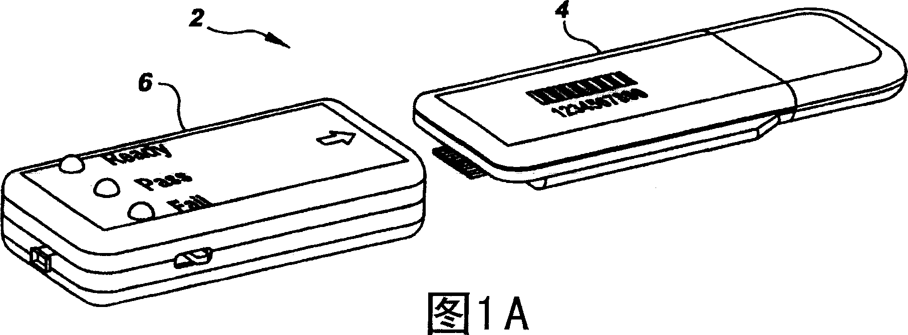
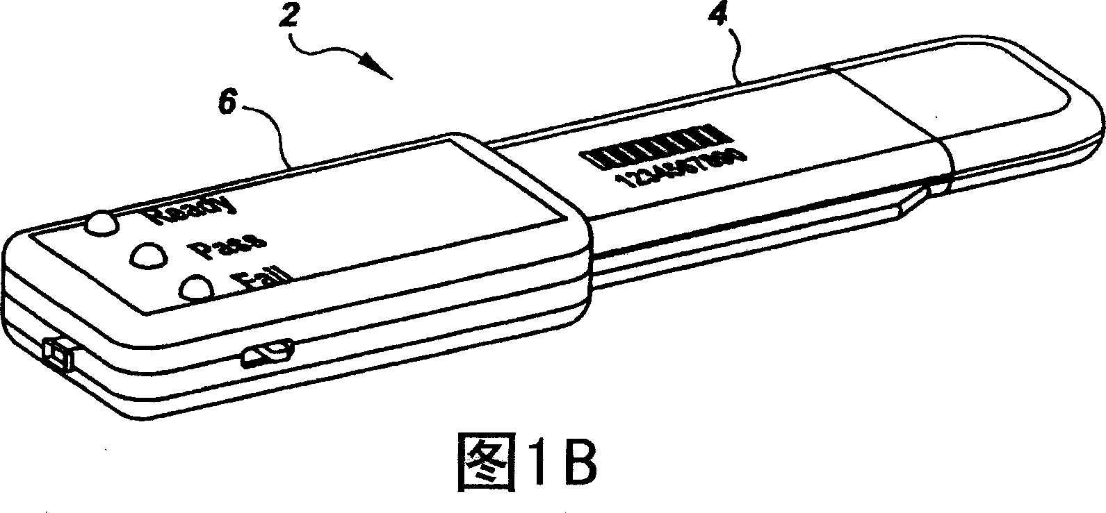
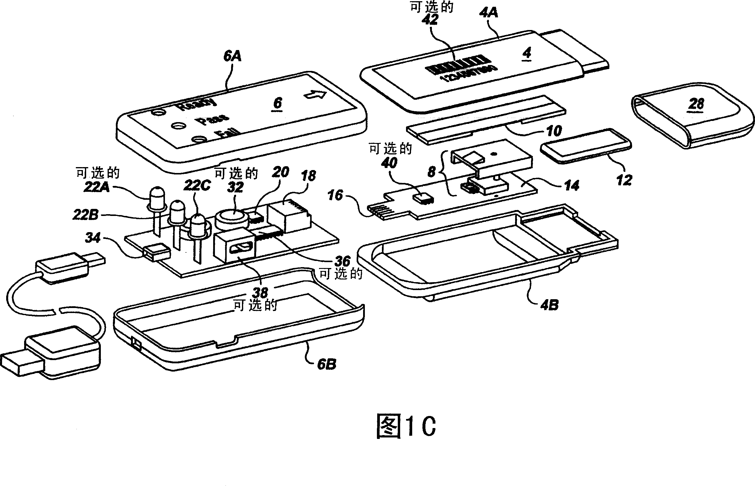
[0018] The present invention provides a semi-disposable rapid diagnostic test device that allows for widespread, point-of-care distribution without the high initial cost and contamination risk of tabletop systems or the optical alignment issues of low-cost handheld assay systems, the low Any misalignment of the sample and reader in a cost-effective handheld assay system can introduce large errors beyond acceptable levels. 1A-1C illustrate a handheld test device 2 according to the present invention. The testing device 2 comprises two main components, the sample cartridge 4 and the reader 6 .

[0019] Figure 1C shows an exploded view of the top part 4A and bottom part 4B of the cartridge 4, and the top part 6A and bottom part 6B of the reader 6, each of which may be molded from low cost plastic. The fluid sample to be analyzed is deposited onto the sample receptor 12 (eg, a collection slip) prior to analysis, and the receptor 12 may then be covered with a plastic "exclusion" ca...


PUM


Abstract

A hand-held optoelectronic test system comprising a cartridge including at least one light source and sensors prealigned to permit acquisition of electro-optic data from a fluid sample reacted with a reagent, such as upon a test membrane in a reaction zone, and a reader which processes the acquired data to identify a physical change in the fluid sample. The cartridge and reader are operable for separate predetermined or controllable finite numbers of tests before becoming disposable.

Description

technical field [0001] The present invention relates generally to in vitro diagnostic (IVD) test systems and, more particularly, to optoelectronic test systems for measuring biological compounds in bodily fluids. Background technique [0002] IVD test systems can be used in a wide variety of medical and environmental conditions. Several assay formats exist, all of which involve reacting a sample of bodily fluid (such as saliva, blood or urine) with a reagent to produce a physically detectable change. An example of such a test system is the Linear Flow Assay (LFA) commonly used in pregnancy testing. In this type of test system, a urine sample flows through a chemical treatment material, such as nitrocellulose, located inside the test device. The presence of the analyte in the urine sample usually produces a visually detectable color on the test strip to indicate pregnancy. [0003] Because the colors, markings, and symbols in the various test systems can vary in intensity ...

Claims


Application Information

Patent Timeline
Patent Type & Authority Applications(China)
IPC IPC(8): G01N21/25G01N33/50
CPCG01N21/8483G01N33/54386G01N33/558G01N33/54388
Inventor R·肖恩·墨菲罗伯特·H·伊布伦顿·A·鲍罗伯特·E·威尔逊
Owner AGILENT TECH INC
Why Eureka
Try Eureka