
Damaged bolt and screw removing devices

A removal, breakage technology, applied in the direction of drilling tool accessories, transportation and packaging, parts of boring machine/drilling machine, etc., can solve the problem of damage to slotted head fasteners, etc.

Inactive Publication Date: 2007-04-25
COMBINED PRODS
View PDF4 Cites 3 Cited by
  • Summary
  • Abstract
  • Description
  • Claims
  • Application Information

AI Technical Summary

Problems solved by technology

Otherwise, slotted head fasteners will be damaged during removal

Method used


Image

  • Damaged bolt and screw removing devices
  • Damaged bolt and screw removing devices
  • Damaged bolt and screw removing devices

Examples


Embodiment Construction

[0041] The present invention provides bit configurations and various bit / thread configurations on a single piece to allow for easier fastener extraction.

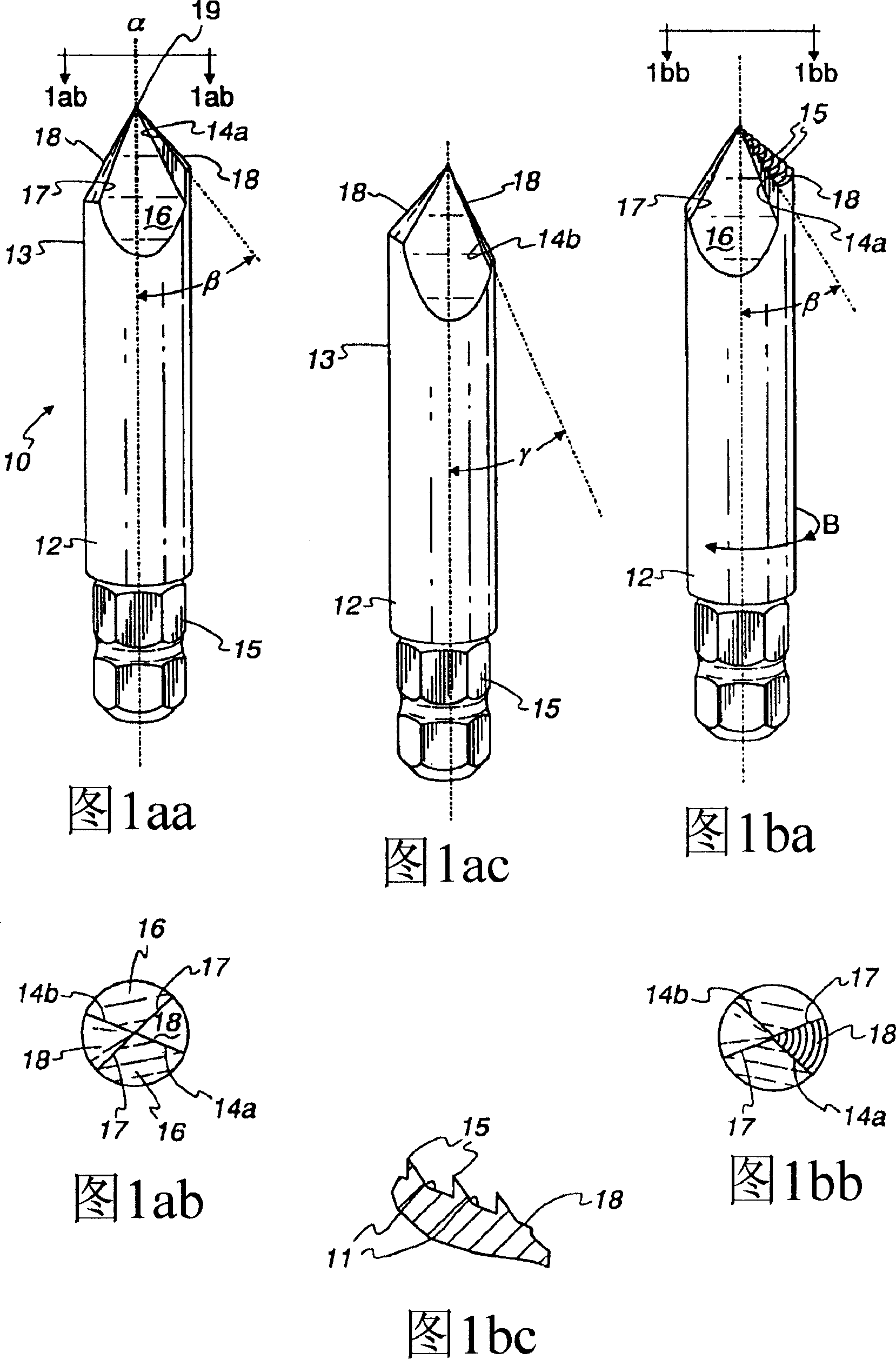
[0042] The salient features of the inventive drill bit, generally indicated by the numeral 10, are provided in FIG. 1aa. As with any typical drill bit, the drill bit generally includes a shank 12 having a first end 13 terminating in a tip 19 . Although the tip 19 is depicted as being generally pointed, a standard split tip may also be utilized such that the cutting surfaces 14 are not coplanar with each other or with the tip. This split-tip configuration makes it possible to minimize and even prevent situations where the drill bit "shifts off" the workpiece. Thus, the arrangement acts as a means for retaining the drill bit on the fastener during the rotational movement of the drill bit.

[0043] The second end 15 of the bit is configured to be received by a rotational torque imparting tool including, but not limited to, a...


PUM


Abstract

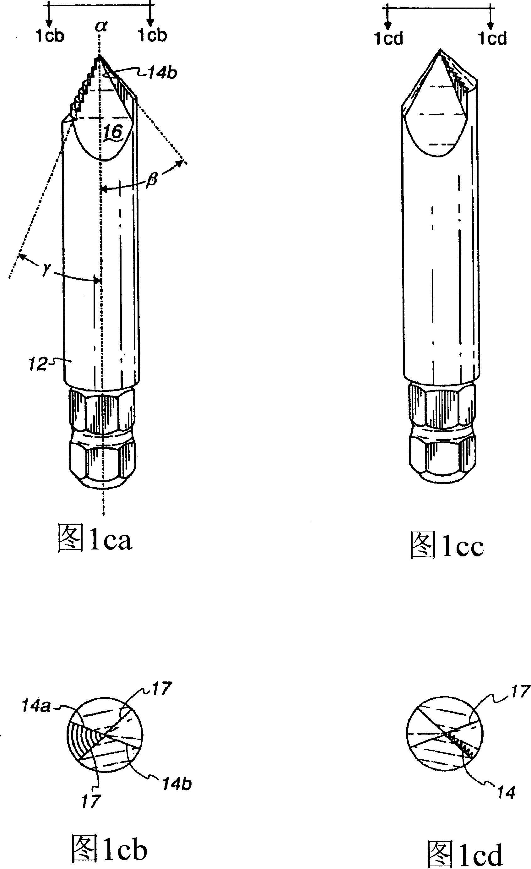
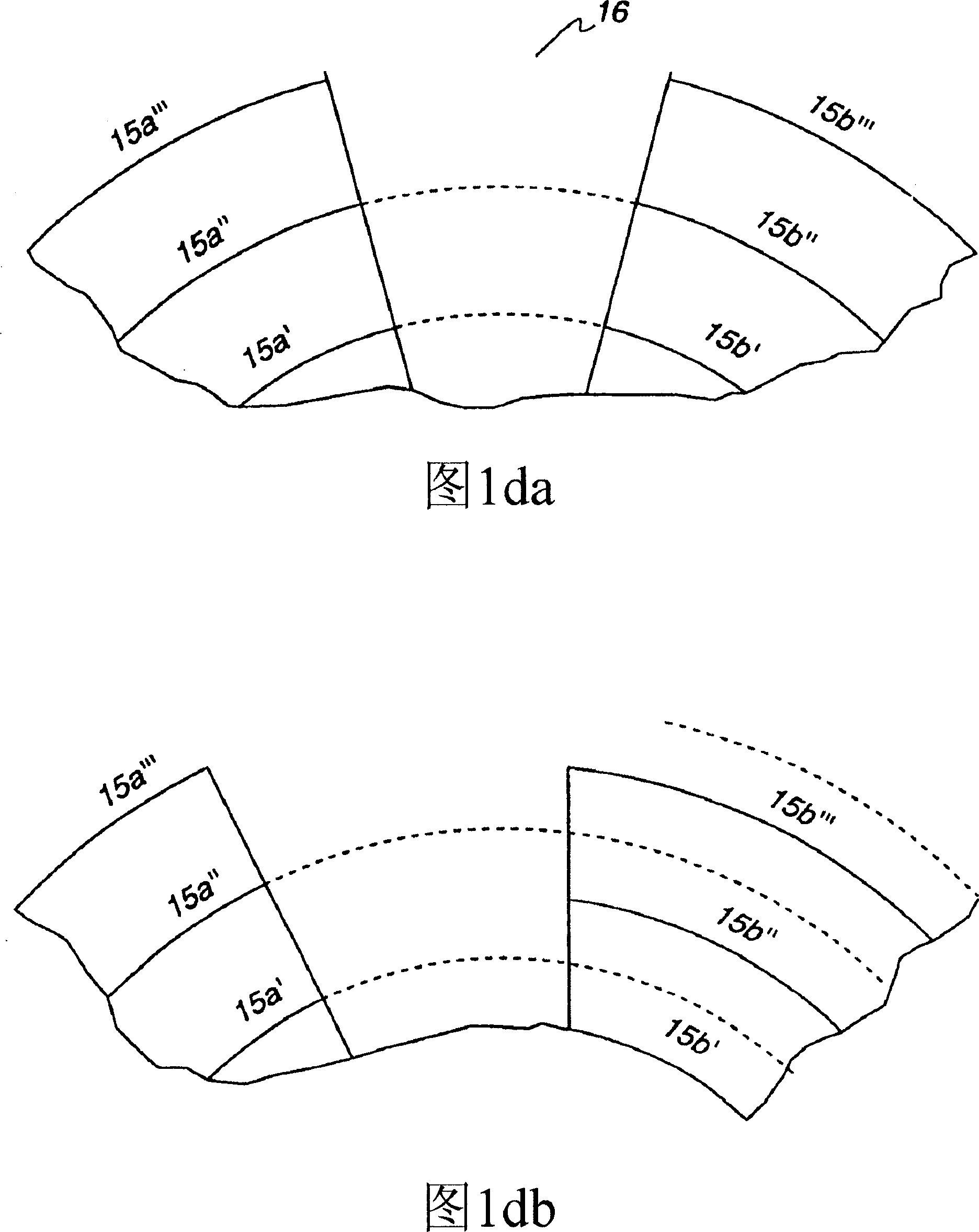
A bit for removing a broken fastener comprises a tip from which extend two or more notches separated by scraping surfaces formed from two-sided frusto-conically-shaped regions. The scraping surfaces are bounded on one side by a cutting edge and on the other side by a non-cutting edge and are configured to cut into the fastener when the bit is rotated in a direction opposite to the fastener's direction of engagement. Specific embodiments include configurations where the cutting edges extend at different angles with respect to the bit axis and where the scraping surfaces comprise a plurality ofserrations.

Description

[0001] This patent application claims the benefit of U.S. Provisional Patent Application No. 60 / 465,506, filed April 25, 2003, and U.S. Applied Patent Application No. 10 / 831,391, filed April 23, 2004. technical field [0002] This invention relates to the field of metal cutting tools, and more particularly, the invention relates to means for removing damaged fasteners that are still embedded or engaged with a workpiece. Background technique [0003] The use of fasteners such as screws, bolts and other threaded joints continues to increase. However, the more a fastener is used, the more likely it is to become rounded, damaged or rendered useless. At that time, those fasteners must be removed, and / or the workpiece must be replaced or discarded. [0004] Various screw removal bits exist. In general, the drill bits are typical in that each rotary tool handle, such as the handle of a screwdriver, is either manual or powered. The second end of the bit is configured to impart a ...

Claims


Application Information

Patent Timeline
Patent Type & Authority Applications(China)
IPC IPC(8): B25B27/18B23B51/00B23B51/10
CPCB23B51/009B23B51/10B23B51/0009B23B51/0081B25B27/18B23B51/00B23B2251/04B23B2251/087B23B2251/14B23B51/00035B23B39/00B25B13/48B23B41/00
Inventor 伯顿·科扎克艾拉·科扎克
Owner COMBINED PRODS
Learn More