Electric cleaner

A vacuum cleaner and electric technology, which is applied to the installation of vacuum cleaner equipment, electrical equipment, and improvement of the efficiency of home appliances, etc., can solve the problems of difficult calibration and large width difference, and achieve the effect of improving control accuracy and improving work efficiency.

Active Publication Date: 2007-05-02
PANASONIC CORP
View PDF0 Cites 14 Cited by
  • Summary
  • Abstract
  • Description
  • Claims
  • Application Information

AI Technical Summary

Problems solved by technology

In the case of very small dust particle size, that is, fine dust, X<
[0013] As mentioned above, the characteristics of vacuum cleaners so far are only for dust of a certain size, and there is a problem that the optimal power supply power control of electric fans cannot be performed according to dust of various particle sizes including fine dust.

Method used


Image

  • Electric cleaner
  • Electric cleaner
  • Electric cleaner

Examples


Embodiment 1

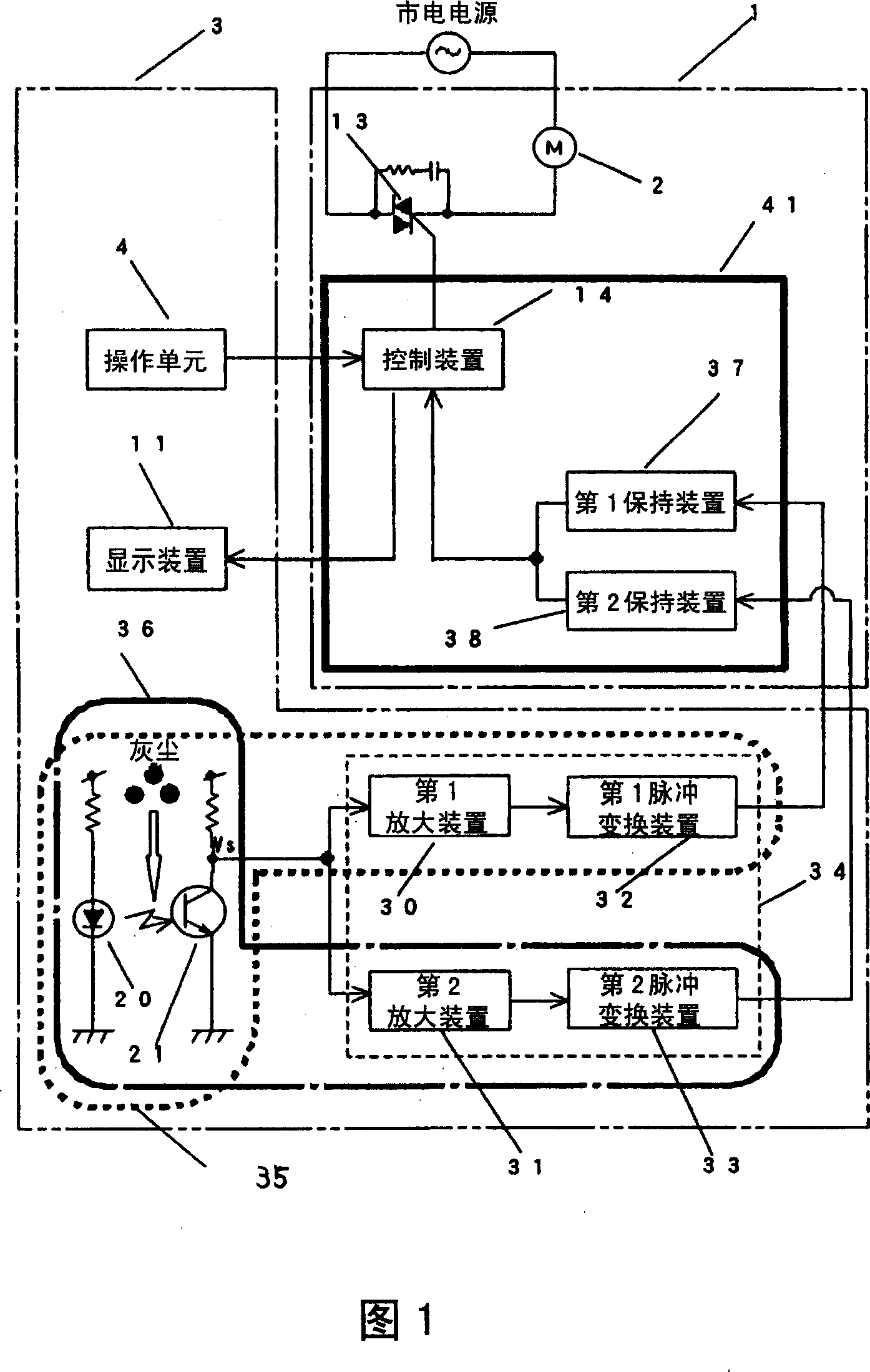
[0038] A first embodiment of the present invention will be described below with reference to FIGS. 1 to 6 . Wherein, for the components that are the same as those in the above-mentioned conventional vacuum cleaner, only the same symbols are attached here, and repeated descriptions thereof are omitted.

[0039] FIG. 1 is a block diagram of a control circuit of a dust display device for an electric vacuum cleaner in Embodiment 1 of the present invention.

[0040] In Fig. 1, 20 is a light-emitting unit composed of infrared light-emitting diodes, etc., and 21 is a light-receiving unit composed of photosensitive tubes, etc. When dust passes between the two, a signal Vs corresponding to the dust will be output. 30 is a first amplifying device composed of an operational amplifier, etc., which amplifies the signal Vs output by the detection unit 22 with a specified first amplification factor. The first amplifying device 30 has amplification and filtering functions, and only outputs a ...

Embodiment 2

[0080] Next, a second embodiment of the present invention will be described using FIG. 7 . Wherein, for the same components as those in the previous existing vacuum cleaner, only the same symbols are attached here, and the detailed description thereof is omitted.

[0081] Fig. 7 is a control block diagram of the dust display device of an electric vacuum cleaner in Embodiment 2 of the present invention. The difference between Embodiment 3 and Embodiment 1 is that a third holding device 50 is provided, and the first dust detection signal and the second dust detection signal It is input to the third holding device 50, and the third holding device 50 outputs a first holding signal corresponding to the first dust detection signal and a second holding signal corresponding to the second dust detection signal based on these two signals.

[0082] The third holding device 50 first judges each degree of dirtiness according to the number of pulses generated by the first dust detection sig...


PUM


Abstract

The present invention provides an electric dust collector capable of always keeping optimal attractive force for various kinds of dust, thereby improving the control precision and efficiency of the power supplied to the electric blower fan. The electric dust collector of the present invention comprises a first dust detecting device(35); a second dust detecting device(36); a first holding device(37)for giving holding time to each signal and outputting a first holding signal based on the first dust detecting signal detected by the first dust detecting device; a second holding device(38)for giving holding time to each signal and outputting a second holding signal based on the second dust detecting signal detected by the second dust detecting device; and a display control device(14)for controlling the power supplied to the electric blower fan based on the first holding signal and the second holding signal. Thus, the dust of different sizes can be detected according to various sizes of the dust respectively so as to improve the control precision of the power according to the size, the kinds and the quantity of dust.

Description

technical field [0001] The present invention relates to a general household or commercial electric vacuum cleaner, and more particularly, to the control of such an electric vacuum cleaner. Background technique [0002] Fig. 8 is a schematic diagram showing a schematic configuration of a conventional electric vacuum cleaner. [0003] In Fig. 8, 1 is an electric vacuum cleaner body, 2 is an electric blower for generating dust suction inside the body 1, and 3 is a hose on which the operation mode of the electric blower 2 can be selected, so that it can be used in different Operating units 4 and 5 that operate under the power supply are extension tubes, 8 is a suction head that is in contact with the surface to be vacuumed and sucks up dust, and 6 is a dust collection chamber for storing the sucked dust. The hose 3 and the dust collection chamber 6 are connected through the suction port 7 provided on the body 1, and the dust collection chamber 6, the hose 3, the extension pipe ...

Claims


Application Information

Patent Timeline
Patent Type & Authority Applications(China)
IPC IPC(8): A47L9/28
CPCY02B40/82Y02B40/00
Inventor 石桥崇文大岛裕夫妹尾裕之福岛雅一伊藤昭人上野圣一
Owner PANASONIC CORP
Why Eureka
Try Eureka