Cutting machine

A cutting machine, a technology for cutting materials, applied in the direction of sawing equipment, sawing components, metal sawing equipment, etc., can solve the problem of not providing one, and achieve the effect of neat appearance

Inactive Publication Date: 2007-05-09
MAKITA CORP
View PDF4 Cites 11 Cited by
  • Summary
  • Abstract
  • Description
  • Claims
  • Application Information

AI Technical Summary

Problems solved by technology

[0011] In the past, with regard to the table saw with the above-mentioned guard, for example, as disclosed in JP 59-501820, a table saw with a warning light in the gua

Method used


Image

  • Cutting machine
  • Cutting machine
  • Cutting machine

Examples


Embodiment Construction

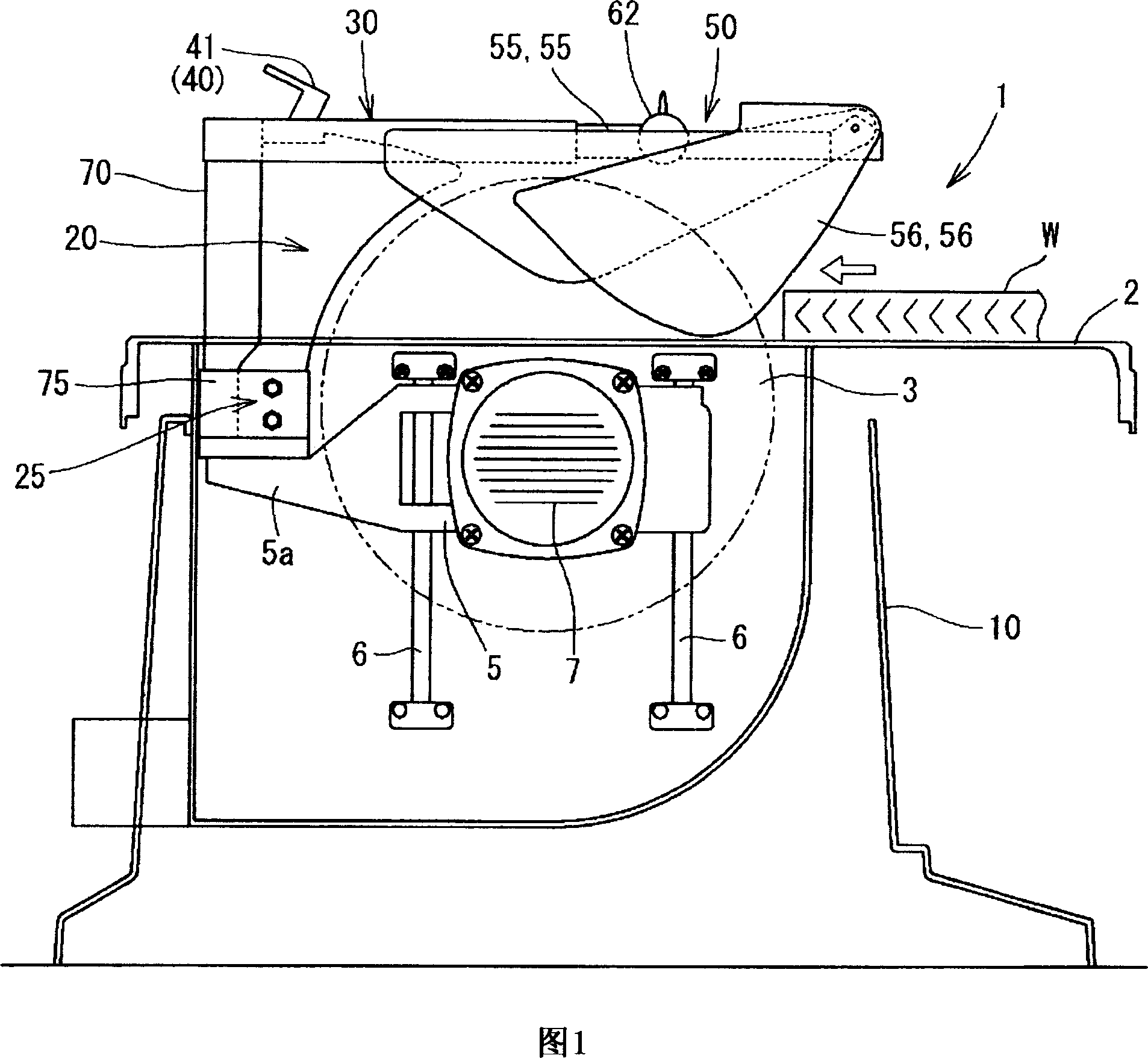
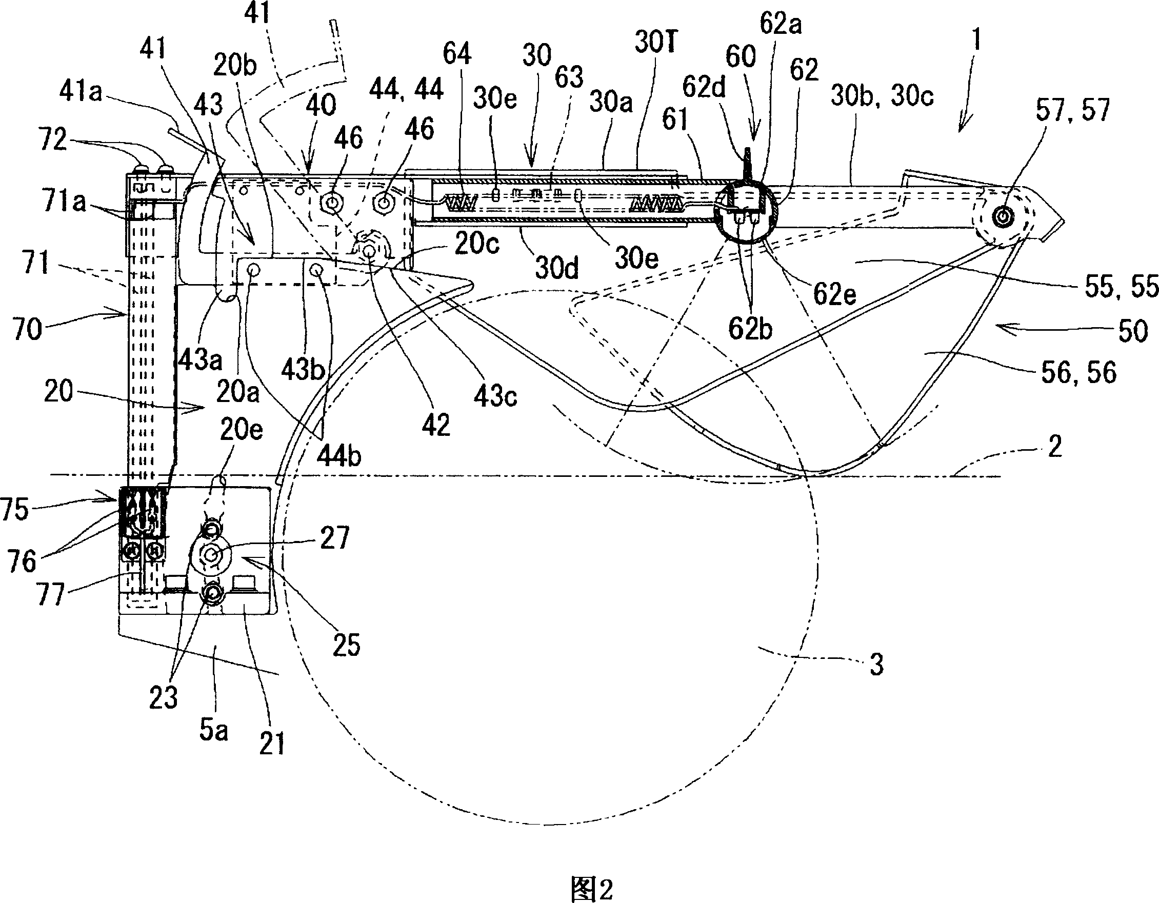
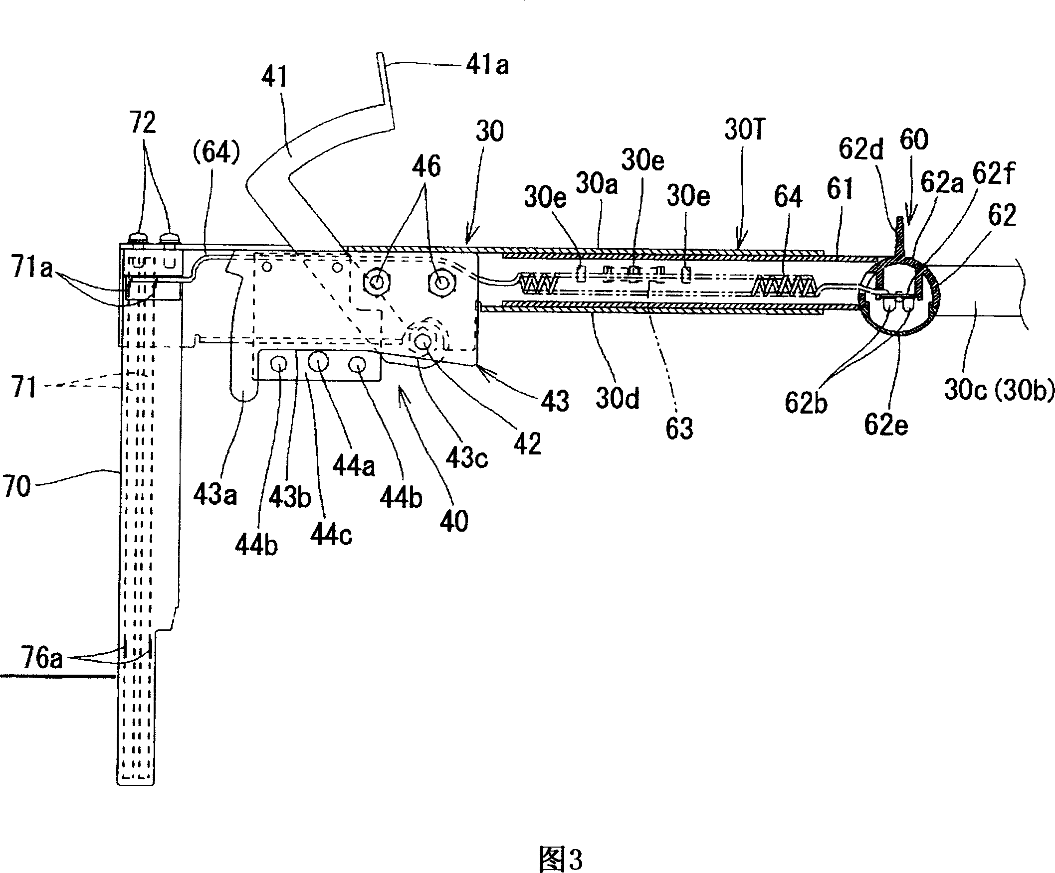
[0034] Next, an embodiment of the present invention will be specifically described based on FIGS. 1 to 13 . FIG. 1 shows the whole of a cutting machine 1 according to a first embodiment described below. This cutting machine 1 is what is called a table saw, and in this embodiment, it is characterized by having an illuminating device 60 for illuminating a cutting part. Other basic configurations of the table saw are the same as conventional ones, and no particular changes are required in this embodiment. Therefore, the overall structure of the cutting machine 1 will be briefly described.

[0035] In FIG. 1 , reference numeral 2 denotes a table on which cutting material W is placed. The table 2 is horizontally supported by a base 10 . A notch is provided substantially at the center of the table 2, and the upper portion of the circular saw blade 3 protrudes upward from the table upper surface through the notch. The saw blade 3 is supported on an elevating base 5 provided on th...


PUM


Abstract

The purpose of the present invention is to provide a cutting machine that performs cutting work by moving the cutting material on the upper workbench protruding from the saw blade, even in a dark place, the cutting material can be easily carried out relative to the saw The ink line alignment work of the sheet. The guard (50) covering the upper part of the saw blade (3) protruding from the upper surface of the workbench (2) is supported on the mounting frame (30) mounted on the riving knife (20), and on this mounting An illuminating device (60) is arranged on the frame (30) to illuminate the cutting site from above.

Description

technical field [0001] The present invention relates to a cutting machine called a table saw in which the upper part of the saw blade protrudes from the upper surface of the table on which the cutting material is placed. Background technique [0002] The so-called table saw is a device configured in a state where the upper part of the circular saw blade protrudes from the upper surface of the table on which the cutting material is placed, and the cutting material placed on the table faces the saw blade and moves in the planar direction. The cutting material is subjected to cutting processing. [0003] A guard covering the saw blade is provided in such table saws so that objects other than cutting material do not affect the saw blade protruding from the upper surface of the table. The guard is provided so as to be openable and rotatable up and down, and can be pushed up by cutting material close to the saw blade to be opened upward. [0004] For example, the technique of su...

Claims


Application Information

Patent Timeline
IPC IPC(8): B23D47/00B23D59/00B25F5/00F21V33/00B27G19/08B27G19/02B27B31/06
Inventor 柴田美德
Owner MAKITA CORP
Why Eureka
Try Eureka