Method of molding radiator, and locative structure

A molding method and positioning structure technology, applied in heat exchange equipment, lighting and heating equipment, workpiece clamping devices, etc., can solve problems such as insufficient tightness of heat dissipation fins, deformation of heat dissipation fin surfaces, and reduced heat dissipation efficiency

Inactive Publication Date: 2007-05-09
AMA PRECISION INC
View PDF0 Cites 3 Cited by
  • Summary
  • Abstract
  • Description
  • Claims
  • Application Information

AI Technical Summary

Problems solved by technology

[0004] However, after the above-mentioned radiating fins are pierced with the heat pipe, when the heat radiating fins are no longer stacked up, since the radiating fins are no longer pierced on the heat pipe, the radiating fins that have been passed on the heat pipe It will form a restoring force that stretches upwards, resulting in insufficient tightness between each heat dissipation fin, so that when it is bumped or squeezed during assembly or transportation, the surface of the heat dissipation fin will often be deformed due to collision, and even the surface of the heat pipe will be deformed. There is a loose phenomenon on the top, so that there is only point or line contact between the heat dissipation fins and the heat pipe, which reduces the overall heat dissipation efficiency
Therefore, in order to improve the above shortcomings, one method is to apply an auxiliary medium between the heat pipe and the heat dissipation fin, such as solder paste hot-melt joint, but this method will inevitably add an additional molding step

Method used


Image

  • Method of molding radiator, and locative structure
  • Method of molding radiator, and locative structure
  • Method of molding radiator, and locative structure

Examples


Embodiment Construction

[0032] The technical content and detailed description of the present invention are described below with reference to the accompanying drawings, but the accompanying drawings are only for reference and description, and are not intended to limit the present invention.

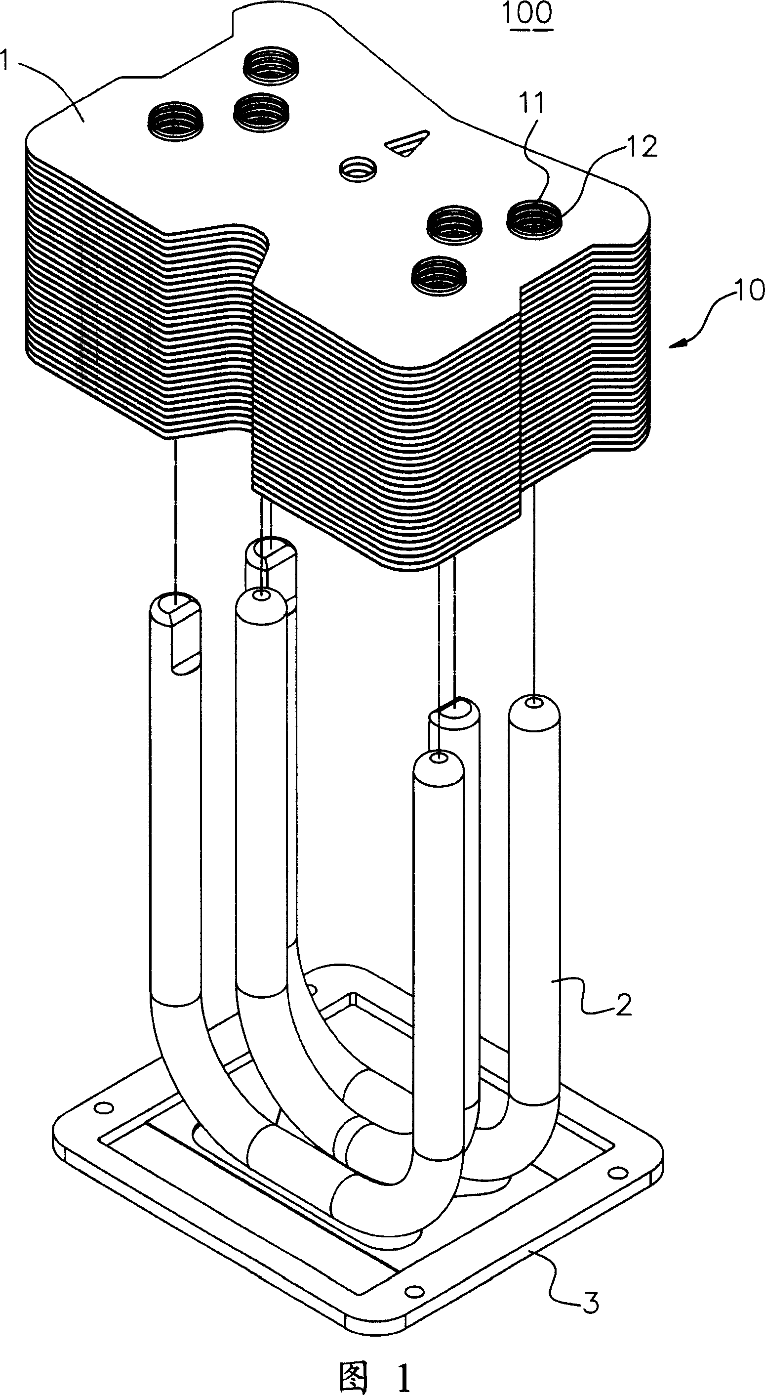
[0033] The present invention is a "forming method of radiator and its positioning structure", and its forming steps are as follows:

[0034] a) First, put the stamped and stacked first cooling fin group on the heat pipe;

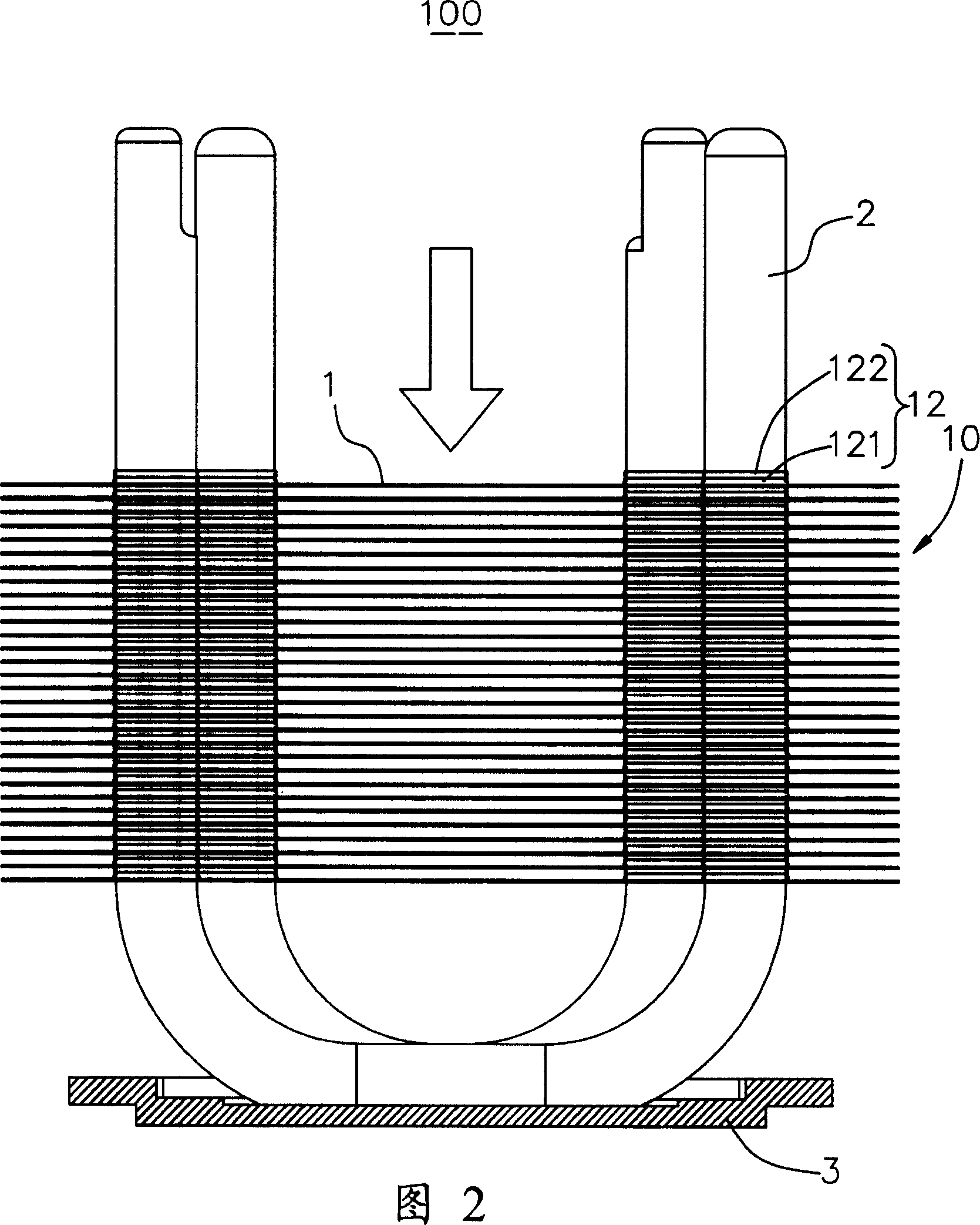
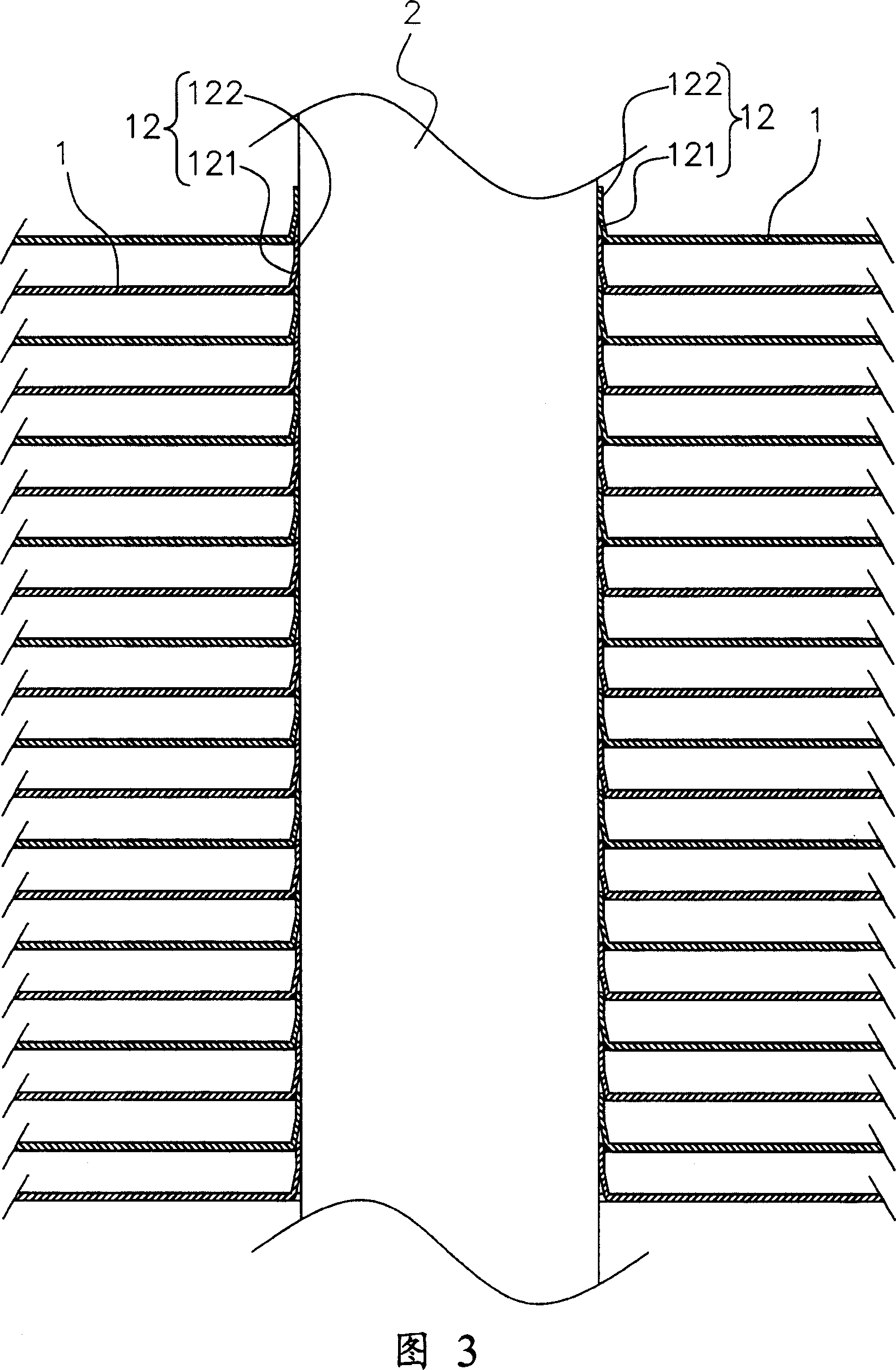
[0035] b) Secondly, set the positioning piece on the heat pipe and attach it to the uppermost heat dissipation fin, and apply a downward force to make the clamping part of the front heat dissipation fin embedded in the conical shape of the rear heat dissipation fin. between the portion and the surface of the heat pipe to reduce the distance between the heat dissipation fins;

[0036] c) Then, put the stamped and stacked second cooling fin group on the heat pipe;

[0037] d) Afterwards, put th...


PUM


Abstract

A technology for forming a heat sink consisting of at least one heat conducting tube and multiple groups of heat-sinking finned sheets includes such steps as passing a heat conducting tube through a laminated first group of finned sheets, attaching a locating plate for applying a pressure down to the group of finned sheets, making said heat conducting tube pass through the second group of heat-sinking finned sheets, and attaching a pressing plate to the top finned sheet. It has high heat sinking efficiency. Its locating structure is also disclosed.

Description

technical field [0001] The invention relates to a forming method of a heat sink and its positioning structure, in particular to a forming method and its positioning structure for stably positioning two or more cooling fin groups against being installed on a heat pipe. Background technique [0002] Generally, in order to increase the heat dissipation rate of the heat dissipation fin group, a heat conduction tube will be pierced on the heat dissipation fin group, and capillary tissue or working fluid will be provided in the heat conduction tube to utilize the capillary tissue or working fluid and the heat dissipation on the heat dissipation fin set. The heat source performs heat exchange, so that the cooling fin set can quickly cool down and dissipate heat. [0003] To thread the heat dissipation fin group on the heat pipe, it is first necessary to punch out a plurality of heat dissipation fins, form a ring wall on the outer edge of the heat dissipation fin, and then penetrate...

Claims


Application Information

Patent Timeline
Patent Type & Authority Applications(China)
IPC IPC(8): B23P21/00B25B11/00B21D28/26F28F1/14
Inventor 陈国星林暄智
Owner AMA PRECISION INC
Why Eureka
Try Eureka