Centered electromagnetic coil and preparation method thereof

An electromagnetic coil, Chinese-style technology, applied in coil manufacturing, inductance/transformer/magnet manufacturing, transformer/inductor coil/winding/connection, etc., can solve the problem of reducing product life, copper wire getting wet, increasing labor and time Cost and other issues

Active Publication Date: 2021-08-13
葛连志
View PDF6 Cites 0 Cited by
  • Summary
  • Abstract
  • Description
  • Claims
  • Application Information

AI Technical Summary

Problems solved by technology

[0003] At present, on the one hand, the copper wires in the electromagnetic coil need to be bundled and fixed, which increases labor and time costs; The fulcrum will cause a gap between the frame body and the upper limit part and the lower limit part due to the principle of thermal expansion and contraction. service life

Method used


Image

  • Centered electromagnetic coil and preparation method thereof
  • Centered electromagnetic coil and preparation method thereof
  • Centered electromagnetic coil and preparation method thereof

Examples


Embodiment 1

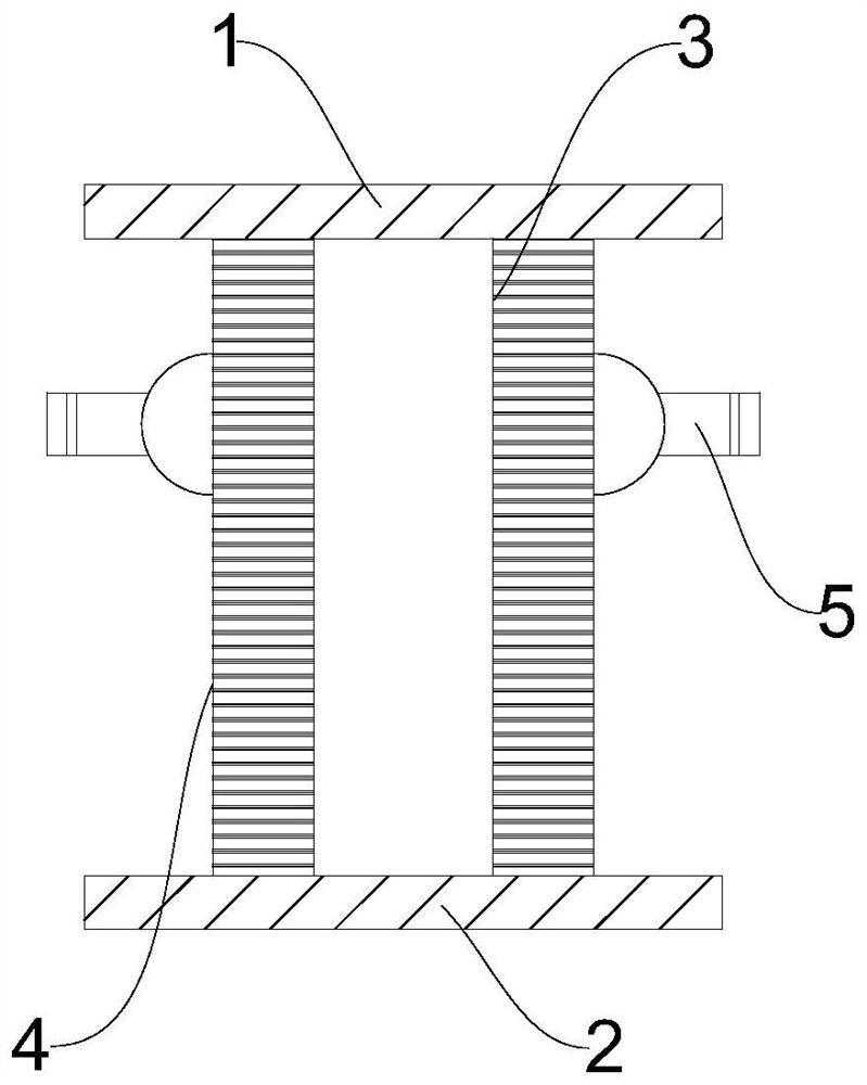
[0037] Please refer to figure 1 , image 3 and Figure 4 Indicated. A homogeneous electromagnetic coil, including a skeleton body, both ends of the skeleton body, respectively, have an upper limit portion 1 and a lower limit bit portion 2, and the skeleton body has a coil winding portion for winding the electromagnetic coil, and the coil winding portion is wrapped around. The electromagnetic coil is connected to the coil winding portion, and the coil winding portion is located between the upper limit portion 1 and the lower limit bit 2.

[0038] In the above embodiment, a centrifugal electromagnetic coil is composed of a skeleton body, a upper limit portion 1, a lower limit bit portion 2, and a coil winding portion, wherein one end of the skeleton body is disposed, and the other end of the skeleton body is set. The middle portion of the portion 2, the middle portion of the skeleton body is the coil winding portion, and the coil winding portion is wound around the electromagnetic coi...

Embodiment 2

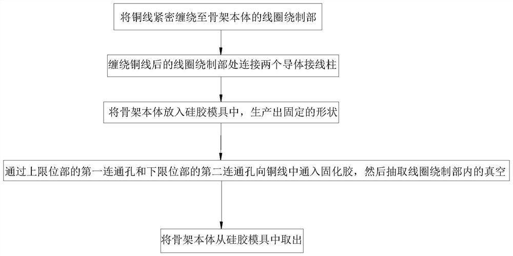
[0051] Please refer to figure 2 Indicated. A hydraulic electromagnetic coil preparation method, including the step of being tightly wound around the coil winding portion of the skeleton body; connecting two conductor terminals at the coil of the copper wire; put the skeleton body into silica gel In the mold, a fixed shape is produced. The cured glue is passed through the second communication hole of the upper limit portion 1, and the second communication hole of the lower limit bit portion 2 is introduced into the copper wire, and then the vacuum in the coil is extracted; the skeleton body Remove from the silicone mold.

[0052] In the above embodiment, the copper wire is first wound around the coil winding portion of the skeleton body, and the coil of the skeleton body is wrapped around the uniform copper wire to connect the two conductor terminals to the above-mentioned copper wire. Used to connect electrical conductive (copper wire wound to the inner layer 3), then place the sk...


PUM


Abstract

The invention provides a centered electromagnetic coil and a preparation method thereof. The invention relates to the technical field of electromagnetic coils. According to the scheme, on one hand, the centered electromagnetic coil comprises a framework body; an upper limiting part and a lower limiting part are arranged at the two ends of the framework body respectively; the framework body is provided with a coil winding part used for winding the electromagnetic coil; and the coil winding part is connected with copper binding posts; and on the other hand, the preparation method of the centered electromagnetic coil comprises the following steps that a copper wire is tightly wound to the coil winding part of the framework body; the coil winding part wound with the copper wire is connected with two conductor binding posts; and the framework body is placed in a silica gel mold to obtain a fixed shape. On one hand, binding and fixing of the copper wire can be omitted, and the labor cost and the time cost are reduced; and on the other hand, silica gel mold opening and glue injection curing are achieved, and the mold cost is low.

Description

Technical field [0001] The present invention relates to the field of electromagnetic coils, and in particular, therefore, in a case of aza electromagnetic coil and a preparation method thereof. Background technique [0002] The electromagnetic coil is established by the magnetic field around the wire, wraps it into a spiral reinforcing magnetic field, that is, the minimum space is used to achieve the highest magnetic field strength, and the wire is wrapped with a layer of insulated paint instead of the ordinary wire is also saved. . [0003] At present, on the one hand, the copper wire in the electromagnetic coil needs to be bundled, increasing the labor and time cost; on the other hand, the product on the market will set the fulcrum at both ends of the copper wire, and the fulcrum is mounted on both ends of the skeleton body. The fulcrum will cause a slit between the skeleton body and the upper limit portion and the lower limit position, and the external environment is contacted...

Claims


Application Information

Patent Timeline
IPC IPC(8): H01F27/28H01F27/30H01F41/04H01F41/082
CPCH01F27/28H01F27/306H01F41/04H01F41/082
Inventor 葛连志
Owner 葛连志
Why Eureka
Try Eureka