Method for preparing textured pattern presenting 3D visual effect through spray painting
A technology of stereoscopic vision and manufacturing method, applied to the device for coating liquid on the surface, the process for producing decorative surface effects, coating, etc., which can solve the problems of coating effects that cannot produce stereoscopic visual experience, etc.
- Summary
- Abstract
- Description
- Claims
- Application Information
AI Technical Summary
Problems solved by technology
Method used
Image

Examples
Embodiment 1
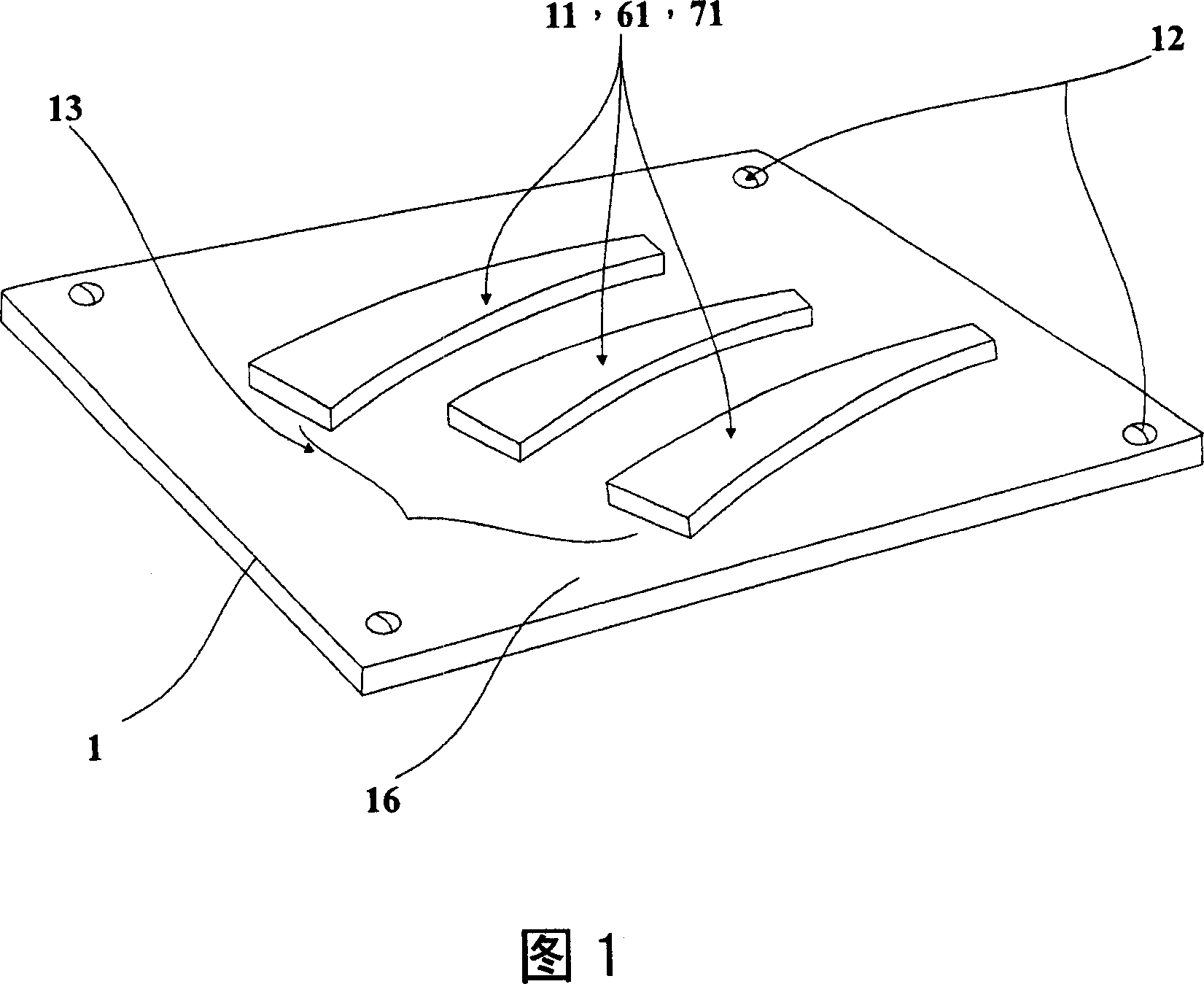
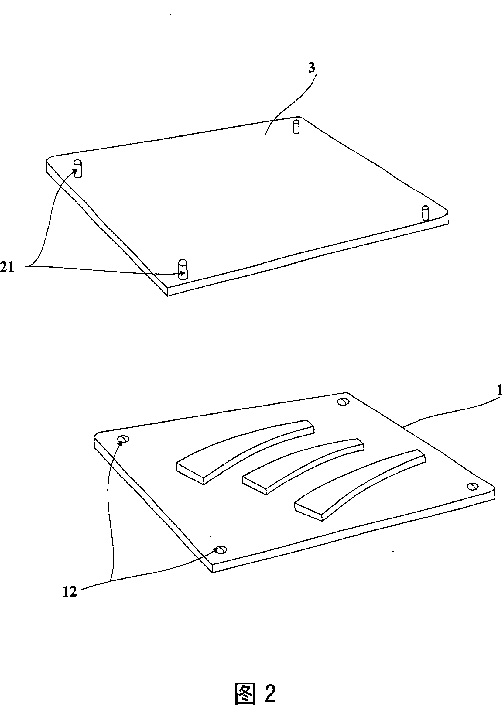
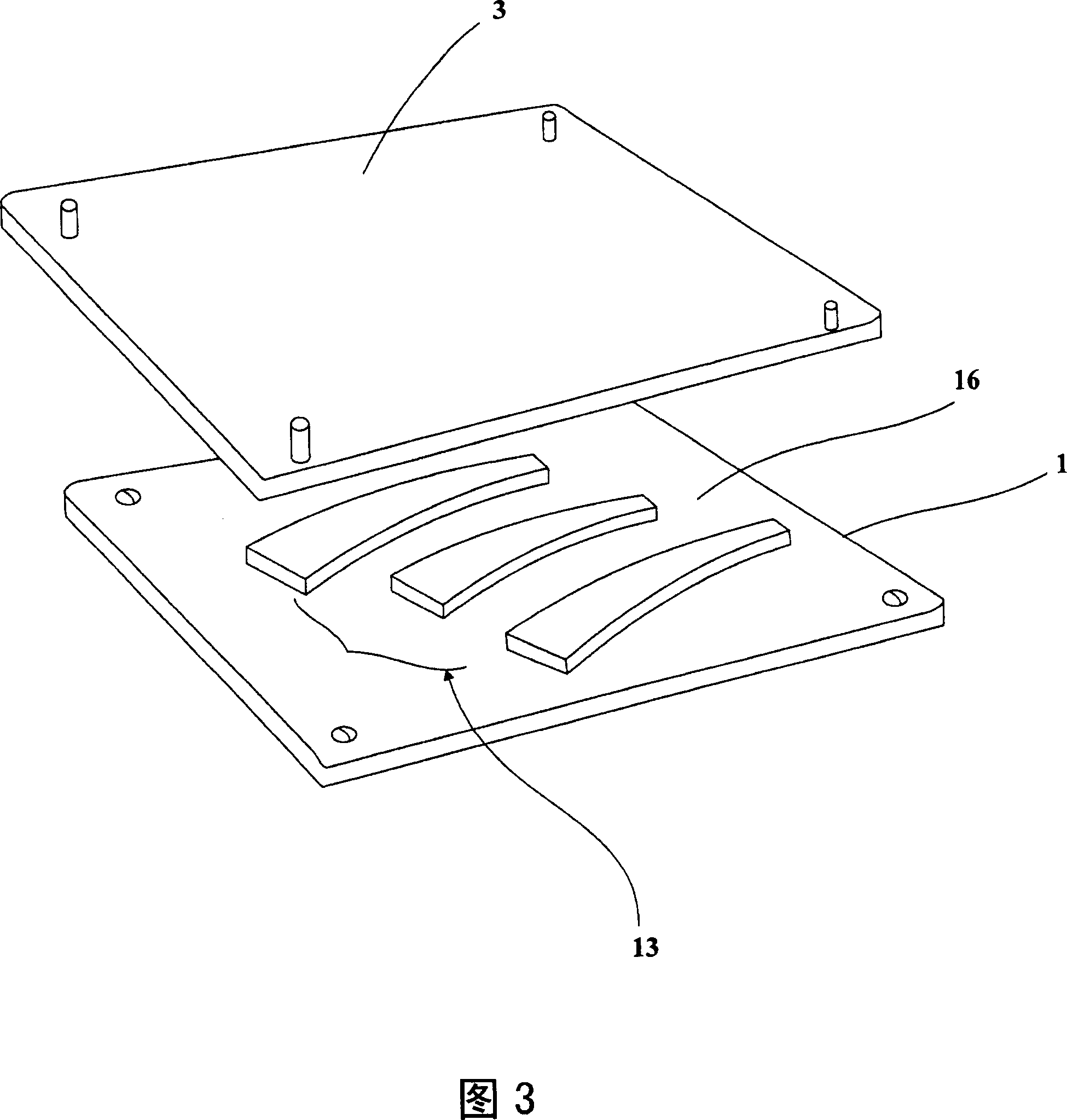
[0051] To make a permanent magnet fixture template 1 (see Figure 1 for details), first attach a rubber magnet 11 to the fixture substrate 16 to make a permanent magnet fixture template with a decorative pattern 13 designed to meet the needs of consumers 1. Match each positioning point 12 with the fixed point 21 of the product 3 to be processed. The positioning studs 12 are only to enable the three-dimensional decorative pattern 17 after coating to be correctly positioned on the surface of the product 3 to be processed, and no positioning is required. The decorative pattern 13 of the rubber magnet 11 of the present invention can be formed by stamping, general engraving, C.N.C engraving and forming, and the entire surface of the rubber magnet is magnetized and arranged. The magnetic field performance of the rubber magnet 11 is fixed, and its magnetic force does not need to be adjusted through an electric current, so it is suitable for relatively simple line shapes.
[0052] Pla...
Embodiment 2
[0057] First, use a planar decorative pattern 130 designed to meet the needs of consumers, and die-cut the rubber magnet 11 into the decorative pattern 13 according to the planar decorative pattern 130, and then attach the decorative pattern 13 to the jig substrate 16 Above, complete a permanent magnetic fixture template 1.
[0058] Pour the fixing glue 15 onto the permanent magnetic jig template 1 with the desired decorative pattern 13, so that the fixing glue can be filled into the jig substrate 16 with the decorative pattern 13, and before the fixing glue 15 is completely dry, put the The product 3 to be processed is placed on the permanent magnetic fixture template 1 and pressed against it, so that a positioning point 12 corresponding to the fixed point 21 below the product 3 is produced, and the positioning point 12 can make the coating The final three-dimensional decorative pattern 17 is correctly positioned on the surface of the product 3 to be processed.
[0059] The ...
Embodiment 3
[0063] The rubber magnet 11 is die-cut into a decorative pattern 13 in the shape of a round hole, and the decorative pattern 13 is pasted on the jig substrate 16 to complete a permanent magnet jig template 1 . (Refer to Figure 4-2, Figure 8-1 and Figure 8-2 for details)
[0064] Place the product 3 to be processed above the permanent magnetic jig plate 1 so that the magnetic field lines of the rubber magnet 11 on the permanent magnetic jig plate 1 penetrate the product 3 to be processed and reach the top of the product 3 to be processed.
[0065] Use the spray gun 5 to evenly coat the paint filled with soft magnetic particles on the product 3 to be processed, and the paint 4 added with soft magnetic particles is arranged and aggregated along the direction 6 of the magnetic field density distribution, and the result is as shown in Figure 8-3. The formed three-dimensional pattern 17.
[0066] Replace the rubber magnet 11 on the permanent magnet fixture template 1 with a hard ce...
PUM
 Abstract
Description
Claims
Application Information
 - R&D Engineer
- R&D Manager
- IP Professional
- Industry Leading Data Capabilities
- Powerful AI technology
- Patent DNA Extraction
Browse by: Latest US Patents, China's latest patents, Technical Efficacy Thesaurus, Application Domain, Technology Topic.
© 2024 PatSnap. All rights reserved.Legal|Privacy policy|Modern Slavery Act Transparency Statement|Sitemap