Hydraulic pressure servo valve

A servo valve and water pressure technology, which is applied in the direction of servo motor components, fluid pressure actuators, circuit components, etc., can solve the problems of not many hydraulic servo valves, no practical effect of servo valves, and poor control characteristics of servo valves. Achieve the effects of suppressing cavitation, small zero drift, and good linearity

Inactive Publication Date: 2007-05-09
HUAZHONG UNIV OF SCI & TECH
View PDF0 Cites 10 Cited by
  • Summary
  • Abstract
  • Description
  • Claims
  • Application Information

AI Technical Summary

Problems solved by technology

According to the test report, this kind of scheme mainly has the following problems: the stability is not very good, the characteristics of low opening are not good, the viscosity of water is low, resulting in insufficient attenuation, the control characteristics of the servo valve are poor, the cavitation is too serious, and the leakage is large , the life is too short, the response frequency is not too high, only 25Hz
The general servo valve mainly works near zero opening, and cavitation is what the servo valve should try to avoid, so this kind of servo valve does not have much practical effect
[0003] Generally speaking, whether it is domestic or foreign, there are not many researches on hydraulic servo valves, and the results are not very satisfactory.

Method used


Image

  • Hydraulic pressure servo valve
  • Hydraulic pressure servo valve
  • Hydraulic pressure servo valve

Examples


Embodiment Construction

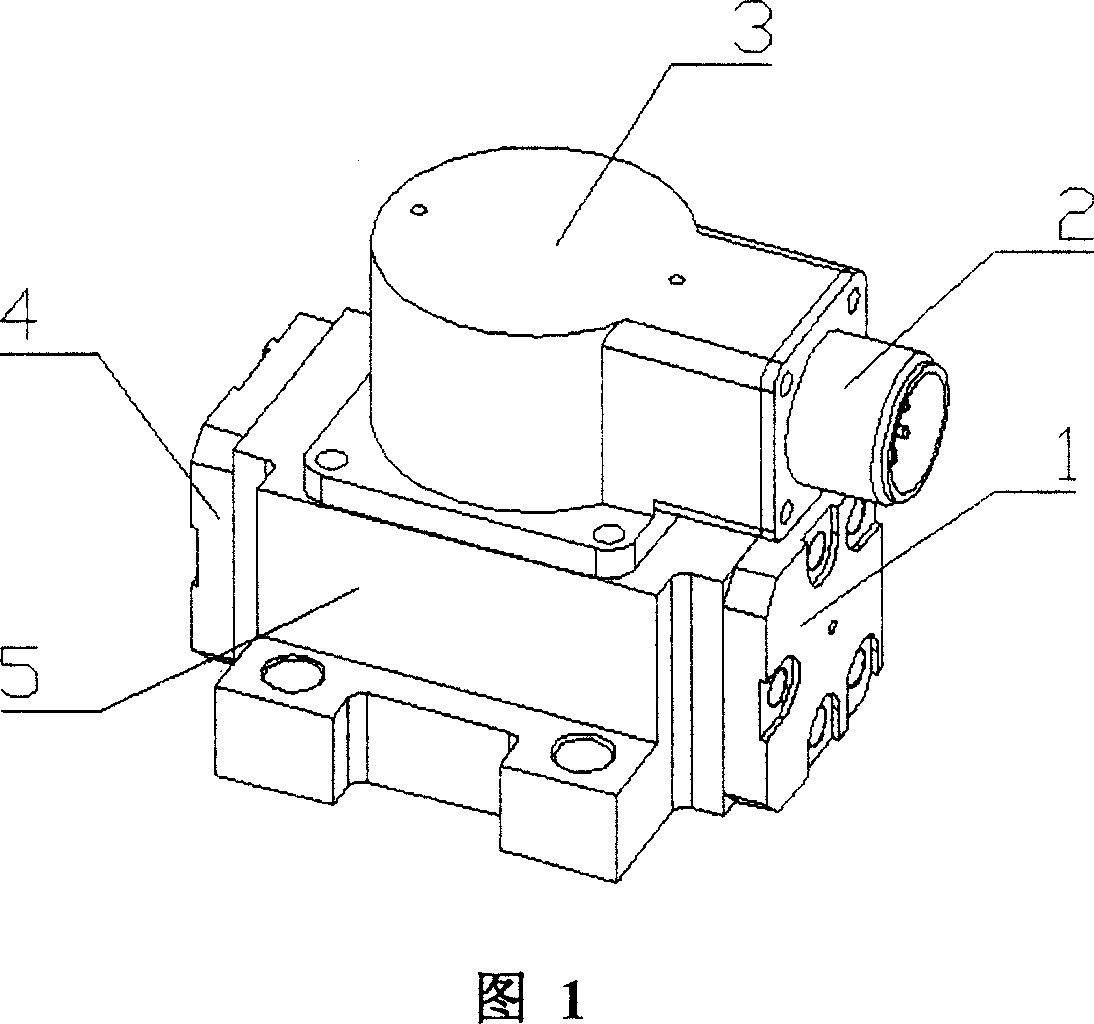
[0030] The present invention is composed of a permanent magnet torque motor, a pre-amplification part and a slide valve power part, and Fig. 1 shows a power line connector 2, a coil casing 3 of the permanent magnet torque motor, and a front end cover 1 and a rear end cover of the slide valve power part 4. Valve body 5.

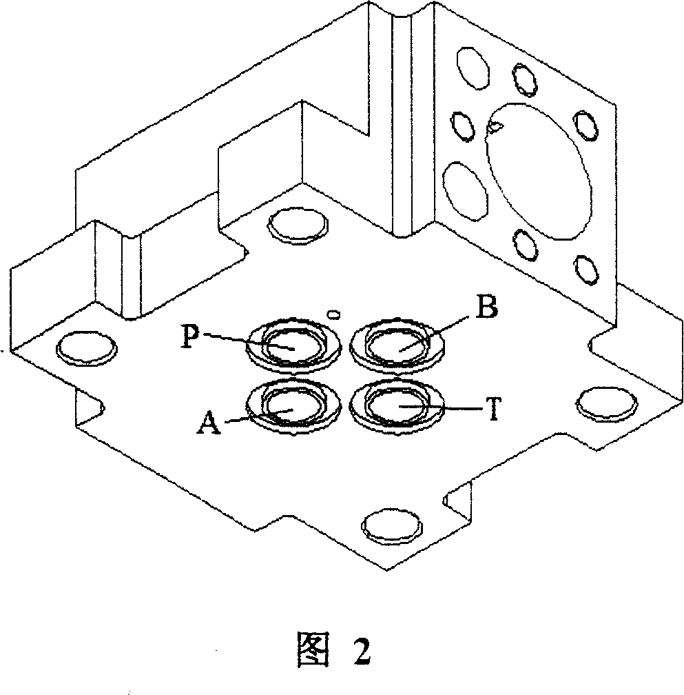
[0031] Fig. 2 is a perspective view of the valve body 5, the bottom surface of the valve body 5 is provided with an input port P, an output port T, a left control port A and a right control port B.

[0032] As shown in Figure 4, Figure 7, Figure 8, and Figure 10, the valve body 5 forms an interference fit with the valve sleeve 9, the valve sleeve 9 forms a sliding fit with the valve core 11, and the two ends of the valve core communicate with the outside world through the valve core stopper 10. Sealing, the spool stopper 10 is fixed with the front end cover 1 and the rear end cover 4 by screws, and a valve body fixing damping hole 42 is opened on the valve bod...


PUM


Abstract

A servo valve of water pressure consists of permanent magnet torque motor, pre-amplification unit and sliding valve power unit. It is featured as arranging filter stopper at two ends of filtering screen end to form concentric circular seam between said stopper and valve body, opening valve body fixed damping hole at valve body between said stopper and valve bush, using water contained in gap between spool and valve bush to form fixed liquid resistance and spool static pressure support of pre -amplification unit.

Description

technical field [0001] The invention belongs to a hydraulic servo control element, in particular to a hydraulic servo valve. Background technique [0002] On July 8, 1993, at the Japan Oil and Pneumatic Society Machinery Promotion Conference, Jun Yamaguchi of Yokohama National University in Japan introduced a servo valve using tap water as the medium. The overall structure is roughly equivalent to the structure of the present invention, and the torque motor part uses Permanent magnet moving iron type, the displacement of the spool is mainly adjusted by the torque balance between the feedback rod and the two ends of the spool, but the displacement of the spool is mainly measured by the displacement sensor, and then fed back to the torque motor for adjustment by the feedback rod, from the filter One-stage throttling is adopted from the device to the front end of the nozzle, the valve core and valve sleeve are tightly sealed, and the zero distance between the nozzle opening and...

Claims


Application Information

Patent Timeline
Patent Type & Authority Applications(China)
IPC IPC(8): F15B13/044F15C3/02
Inventor 聂松林朱玉泉贾国涛张仲良
Owner HUAZHONG UNIV OF SCI & TECH
Why Eureka
Try Eureka