
Signal multiplexing and demultiplexing device

A multiplexing device and signal multiplexing technology, which is applied in the direction of multiplexing communication, frequency division multiplexing system, electrical components, etc., can solve the problems of realizing large complexity and so on

Active Publication Date: 2007-05-09
ZTE CORP
View PDF2 Cites 2 Cited by
  • Summary
  • Abstract
  • Description
  • Claims
  • Application Information

AI Technical Summary

Problems solved by technology

[0012] However, the device implemented in the invention "frequency offset diversity receiver" increases the process of signal transformation between signal multiplexing and demultiplexing, so there is great complexity in the realization of the whole process. In addition, the application of the invention The range aspect is targeted at RF signals

Method used


Image

  • Signal multiplexing and demultiplexing device
  • Signal multiplexing and demultiplexing device

Examples


Embodiment Construction

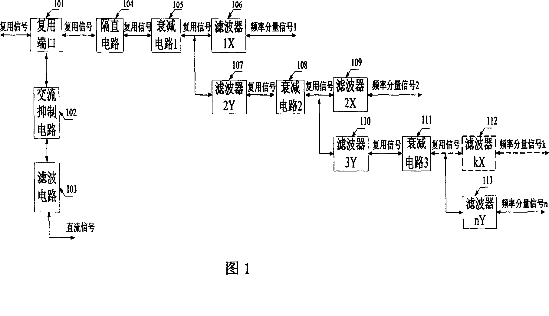
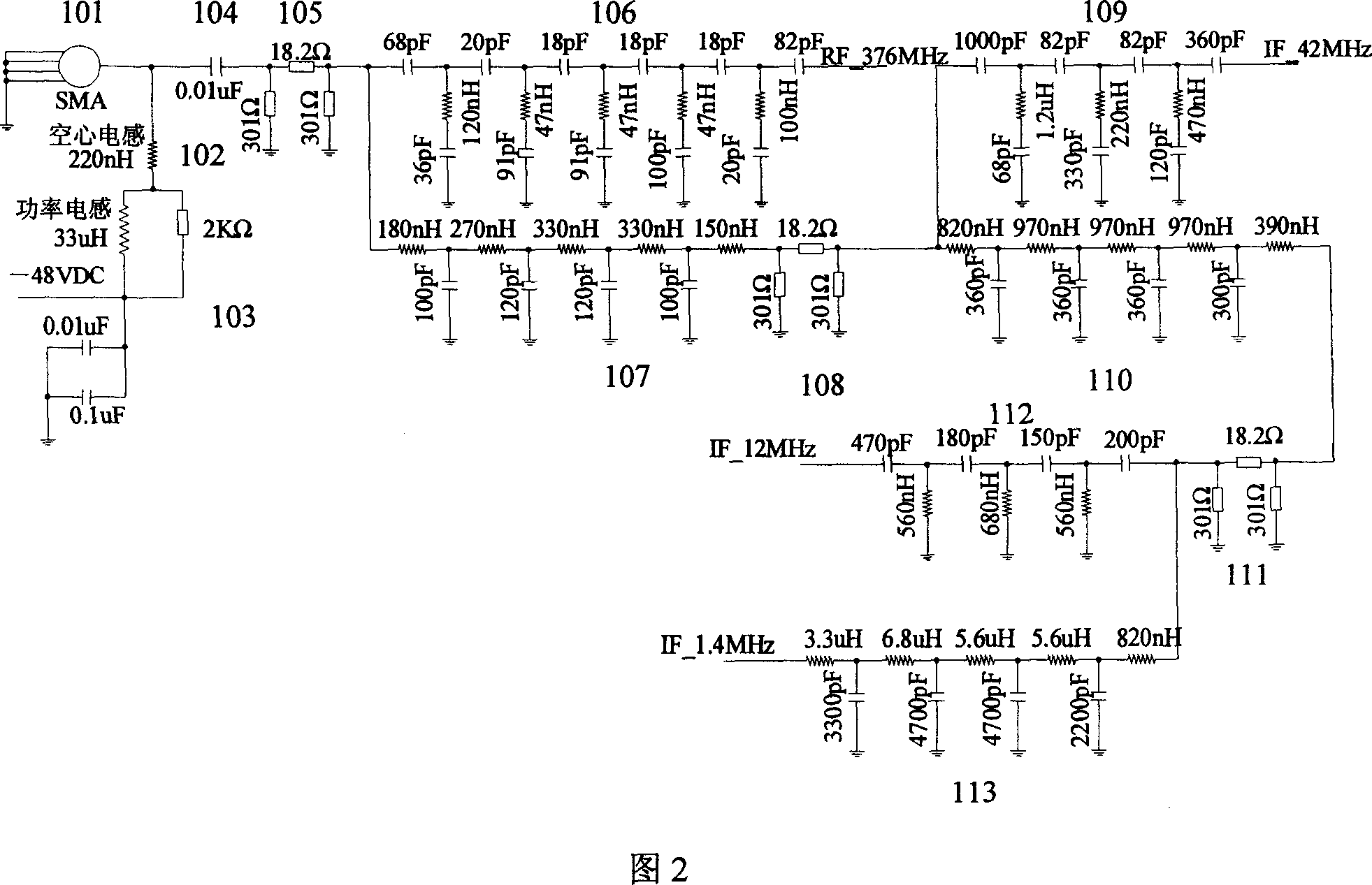
[0041] The device of the present invention comprises the following parts, common multiplexing interface unit 101, AC suppression circuit unit 102, filter circuit unit 103, DC blocking circuit unit 104, attenuation circuit units 1-3 (105 / 108 / 111) and the first A filter unit 1X˜kX (106 / 109 / 112) where 1

[0042] The common multiplexing interface unit 101 is a physical interface for multiplexing signal input and output; the AC suppression circuit unit 102 separates the DC signal from the multiplexing signal; the filtering circuit unit 103 completes the filtering process of the DC signal; the DC blocking circuit unit 104 Complete the isolation of the DC signal in the multiplexing signal; the attenuation circuit unit 1~3 (105 / 108 / 111), mainly complete the power attenuation of the superimposed signal; the filter unit 1X~kX (106 / 109 / 112) is some basis The frequency of the signal to be separated is designed to meet a ce...


PUM


Abstract

The device consists of the public multiplexing interface unit, the DC separation circuit unit, the decay circuit unit, the AC restraint and filter circuit unit, the 1st filter unit and the 2nd filter unit. The 1st filter unit is in use for separating the frequency component signal while the 2nd filter unit is in use for separating remain signal other than frequency component signal. The same device, i.e. the hi-pass and low-pass filters satisfying a certain feature, realizes the multiplexing and de- multiplexing in this invention. These filters separate various frequencies of the multiplexing signal in a certain order and send them to the related frequency output port. The de-multiplexing process is an opposite process. The device not only raises the transfer medium utility, reduces the number of interfaces, lowers the cost, but also is easy of maintenance.

Description

technical field [0001] The invention relates to the field of signal transmission in communication systems, in particular to a device for multiplexing and demultiplexing multiple frequency signals, including direct current signals, transmitted on the same cable by frequency division multiplexing. Background technique [0002] In the field of communication, the transmission of signals such as radio frequency signals, intermediate frequency signals, low frequency signals, and DC feed signals is an inevitable problem. For some systems, there are multiple frequency signals at the same time. If a transmission medium is specially provided for each frequency signal, the system will become more complicated when there are many types of frequency signals, and the types of interfaces and costs will increase. At the same time Decrease system maintainability. Therefore, it becomes necessary to multiplex multiple frequency signals on the same medium for transmission. [0003] In terms of...

Claims


Application Information

Patent Timeline
Patent Type & Authority Applications(China)
IPC IPC(8): H04J1/00
Inventor 周嵘朱红军张来喜谢利超郝磷
Owner ZTE CORP
Learn More