
Vehicle body front part structure of vehicle

A technology of front structure and automobile body, applied in the direction of upper structure, upper structure sub-assembly, vehicle parts, etc., can solve the problems of pitching and swaying, failure to obtain longitudinal beam axial bending deformation, impact cannot be effectively absorbed, etc. Achieve the effect of suppressing the pitch and roll phenomenon

Inactive Publication Date: 2007-05-09
DAIHATSU MOTOR CO LTD
View PDF1 Cites 8 Cited by
  • Summary
  • Abstract
  • Description
  • Claims
  • Application Information

AI Technical Summary

Problems solved by technology

[0003] However, when the conventional structure is adopted in which the apron member is arranged behind the front end of the side member, when the vehicle collides, the input force acting on the side member is not effectively transmitted from the side member to the apron member, and the In some cases, there is a possibility of upward bending and deformation of the stringer, so the axial bending deformation of the stringer cannot be obtained
[0004] In addition, in the conventional structure, there is a possibility of pitching and rolling during a collision, and the rear of the vehicle body is suspended in the air at this time, resulting in the problem that the impact generated by the collision cannot be effectively absorbed

Method used


Image

  • Vehicle body front part structure of vehicle
  • Vehicle body front part structure of vehicle
  • Vehicle body front part structure of vehicle

Examples


Embodiment Construction

[0018] Hereinafter, embodiments of the present invention will be described based on the drawings.

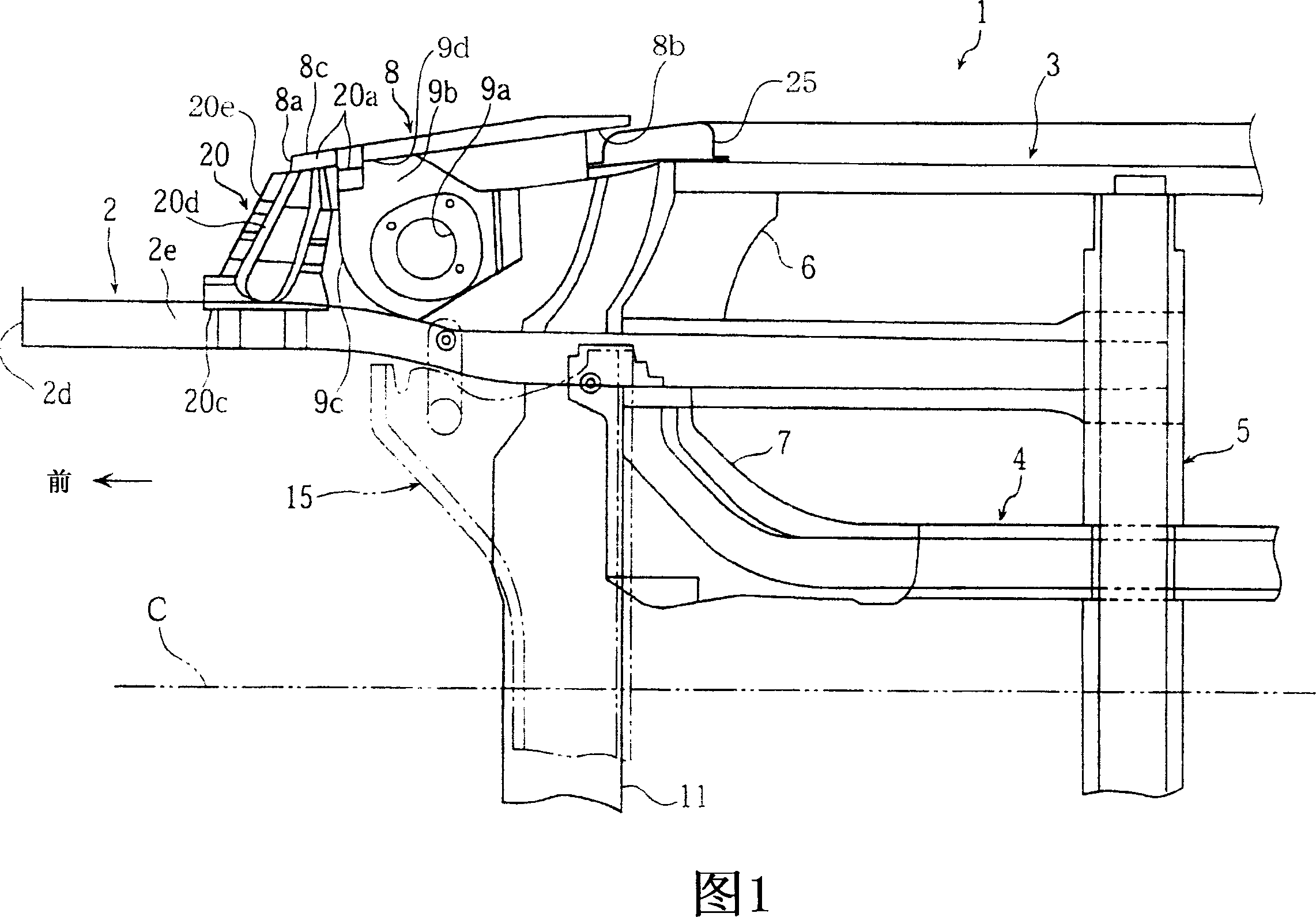
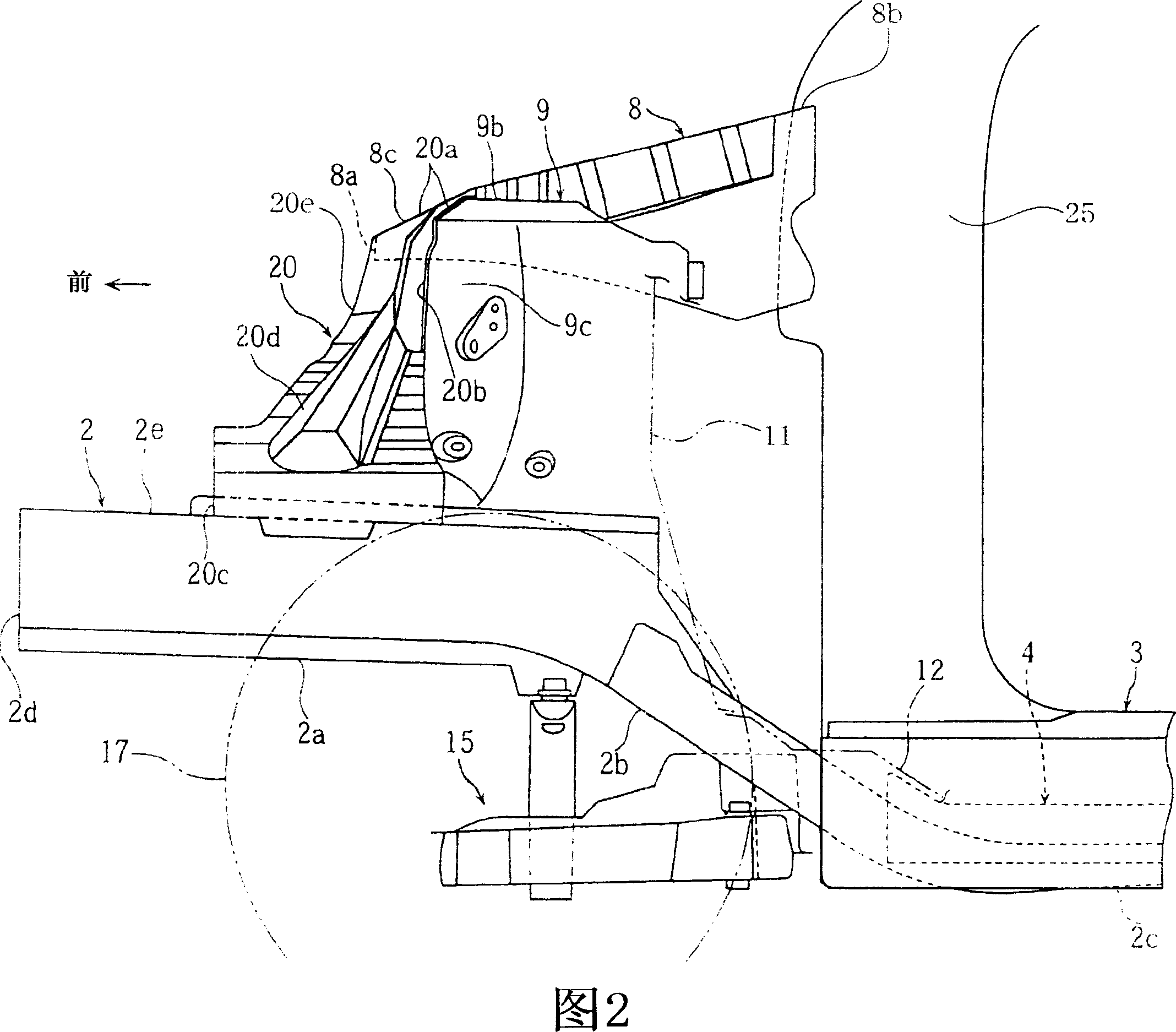
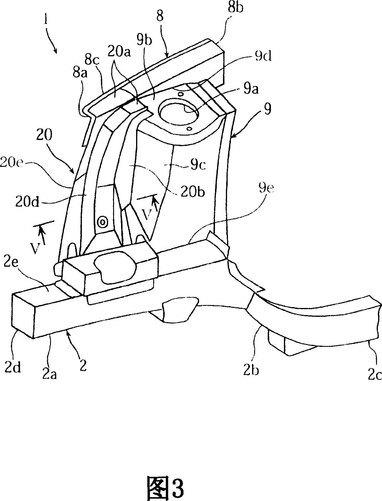
[0019] Accompanying drawing 1-5 has described the vehicle front body structure according to an embodiment of the present invention, and wherein Fig. 1 and Fig. 2 are the top view and the side view of front body frame respectively, Fig. 3 is the perspective view of front body frame, Fig. 4 and Fig. 5 is a front view and a sectional view (vertical section along the section line V-V in Fig. 3) of the rigid part, respectively.

[0020] In Fig. 1, reference numeral 1 denotes a front body frame of a vehicle, which mainly includes: left and right front side members 2, 2 extending longitudinally along the vehicle; left and right rocker rails (rocker rail) 3, 3, which Located on the lateral outsides of the left and right front longitudinal beams 2, 2, and extending substantially along a direction parallel to the front longitudinal beams 2; And basically extending along the direction par...


PUM


Abstract

A vehicle body front part structure of a vehicle capable of suppressing the upward deformation of side members and pitching in collision by securely transmitting an input in the collision from the side members to an apron member. Rigid members (20) are fixedly installed across the front end part (8c) of the apron member (8) and the side members (2), and the forward parts of the rigid members (20) are tilted diagonally downward so as to form a roughly linear shape from the apron member (8) toward the side members (2) as viewed from the side of the vehicle to distributedly transmit the input into the side members in the collision of the vehicle to the apron member (8) through the rigid members (20) and to suppress the upward deformation of the side members (2) by the rigid member (20).

Description

technical field [0001] The invention relates to a front structure of an automobile body, wherein a baffle member is arranged above a pair of left and right longitudinal beams, the longitudinal beams extend along the longitudinal direction of the vehicle, and the front end of the baffle member is located behind the front end of the longitudinal beams. Background technique [0002] In recent automobiles, in order to improve the appearance of the automobile, for example, a structure in which headlights are arranged to extend from the front of the vehicle body to the side of the vehicle body by turning each headlight over a front end corner is often adopted. When this structure is adopted, in order to ensure the installation space of the headlights, the left and right fender members connected to the front pillar are usually arranged so that the front ends of the fender members are located behind the front ends of the left and right side beams, and the fenders The member and the ...

Claims


Application Information

Patent Timeline
IPC IPC(8): B62D25/08
CPCB62D25/082B62D25/088
Inventor 玉木善规松下和彦川本康雄
Owner DAIHATSU MOTOR CO LTD
Learn More