Exhaust frame for a motor vehicle, fixing device comprising such frame, and method for fixing such frame

A motor vehicle and exhaust pipe technology, which is applied in the direction of exhaust device, power device, and power device gas intake, etc., can solve the problems of vibration reduction, complicated assembly of fixing device, and inability to place the fixing device

Inactive Publication Date: 2007-05-09
RENAULT SA
View PDF0 Cites 10 Cited by
  • Summary
  • Abstract
  • Description
  • Claims
  • Application Information

AI Technical Summary

Problems solved by technology

However, given its overall size, such fixtures cannot be placed close enough to the longitudinal member that the transmitted vibrations are substantially reduced
Another solution consists in strengthening the parts that make up the fixture, but this makes the assembly of the fixture more complicated

Method used


Image

  • Exhaust frame for a motor vehicle, fixing device comprising such frame, and method for fixing such frame
  • Exhaust frame for a motor vehicle, fixing device comprising such frame, and method for fixing such frame
  • Exhaust frame for a motor vehicle, fixing device comprising such frame, and method for fixing such frame

Examples


Embodiment Construction

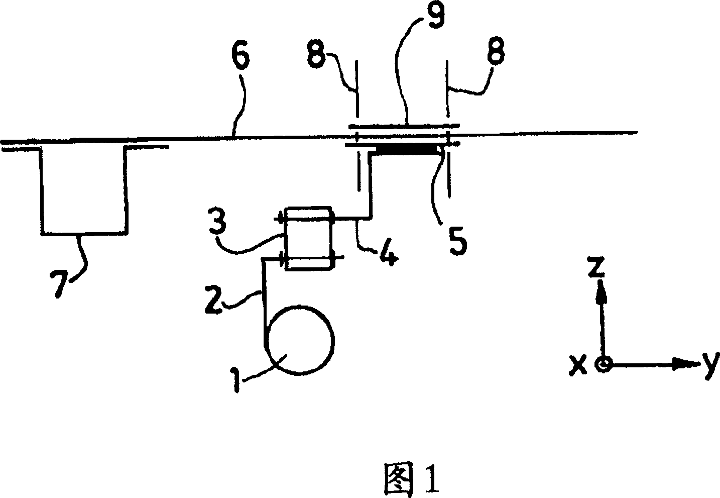
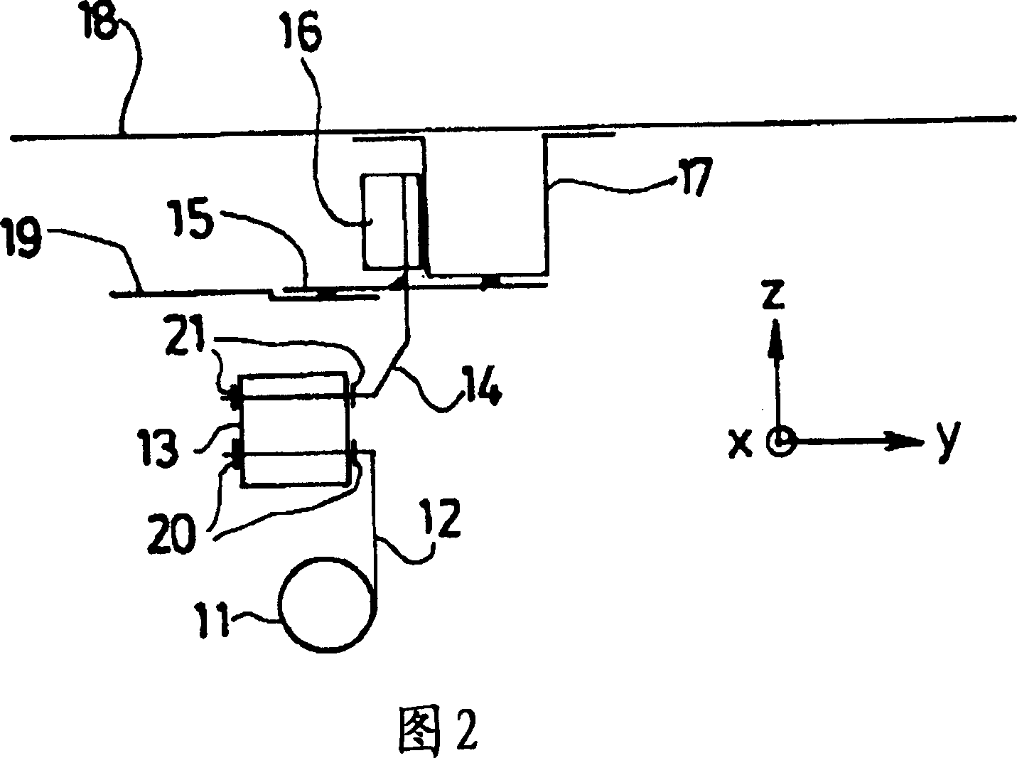
[0023] In the figures, the directions x, y and z represent the longitudinal, transverse and vertical directions of the vehicle, respectively, and the axis x points towards the rear of the vehicle.

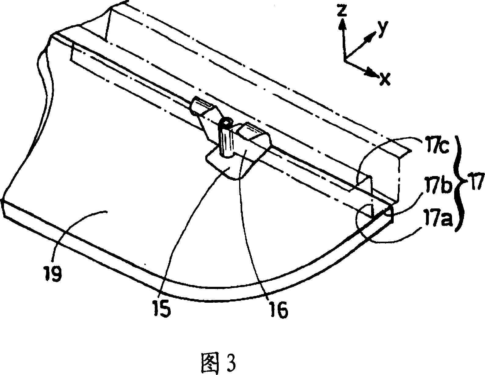
[0024] FIG. 2 schematically shows a fixing device for a motor vehicle exhaust pipe 11 according to the invention. The device includes an exhaust pipe support rod 12 , a vibration damping filter 13 and a metal exhaust pipe support, and the metal exhaust pipe support includes a second support rod 14 , a reinforcing plate 15 and a fixing piece 16 .

[0025] Throughout the description, the term "rod" denotes a metallic elongated element of hollow or solid cylindrical cross-section. However, it is also possible to use differently shaped cross-sections for the rod. The rod is sufficiently rigid so as not to deform under the weight or vibration of the exhaust pipe.

[0026] The fastening device according to the invention is more particularly, though not limited to, an underlying motor v...


PUM


Abstract

The invention relates to a simplified exhaust mounting comprising: a metallic support wire (14) having a lower end which is to be connected to the exhaust of the vehicle (11); a metallic reinforcing plate (15) which is crossed essentially perpendicularly by the upper end of the wire and is soldered thereto; and a metallic fixing part (16) which is fixed to the upper end of the wire, following the axis thereof. The invention also relates to a method for fixing said mounting, according to which the mounting fixing part is soldered to an essentially vertical wall of the girder (17), and the reinforcing plate (15) is soldered essentially horizontally to the girder (17) and the sub-floor (19). The inventive fixing of the mounting enables a good transmission of the vibrations to the girder of the vehicle.

Description

technical field [0001] The invention relates to a motor vehicle exhaust pipe bracket, a fixing device provided with such a bracket and a method for fixing such a bracket. Background technique [0002] A motor vehicle exhaust pipe fixing device according to the prior art is schematically represented in FIG. 1 . The engine exhaust pipe 1 is welded to a support rod 2, the other end of which is inserted and maintained substantially horizontally in a rubber filter 3 for vibration damping. In the filter 3, above the supporting rod 2 of the exhaust pipe, one end of another rod 4 is inserted, which is basically in the form of a step, and the other horizontal end of the rod 4 is welded under a reinforcing plate 5 . The plate is screwed to the vehicle floor 6 , which is itself supported by longitudinal members 7 . The bolt shank is indicated by reference 8 in the figure. Another reinforcing plate 9 is generally placed on the other side of the floor 6 relative to the first plate 5 ...

Claims


Application Information

Patent Timeline
Patent Type & Authority Applications(China)
IPC IPC(8): F01N7/18F01N13/18B60K13/04
CPCF01N13/1822B60K13/04
Inventor P·科瓦尔斯基G·雅姆塞
Owner RENAULT SA
Why Eureka
Try Eureka