Hybrid vehicle control

A technology for a hybrid vehicle and a control system, which is applied in the field of the brake control system of the hybrid vehicle, can solve the problems of high state of charge of the battery, limiting the regenerative braking of the motor/generator, etc.

A technology for a hybrid vehicle and a control system, which is applied in the field of the brake control system of the hybrid vehicle, can solve the problems of high state of charge of the battery, limiting the regenerative braking of the motor/generator, etc.

CN1962332AInactive Publication Date: 2007-05-16NISSAN MOTOR CO LTD

Image

  • Hybrid vehicle control
  • Hybrid vehicle control
  • Hybrid vehicle control

Examples


Embodiment Construction

[0030] Selected embodiments of the present invention will be described below with reference to the drawings. According to the content disclosed in this application, those skilled in the art can easily understand that the description of the embodiments of the present invention provided below is only for illustration purposes and does not constitute a limitation of the present invention. The present invention is defined by the appended claims and their equivalent replacements .

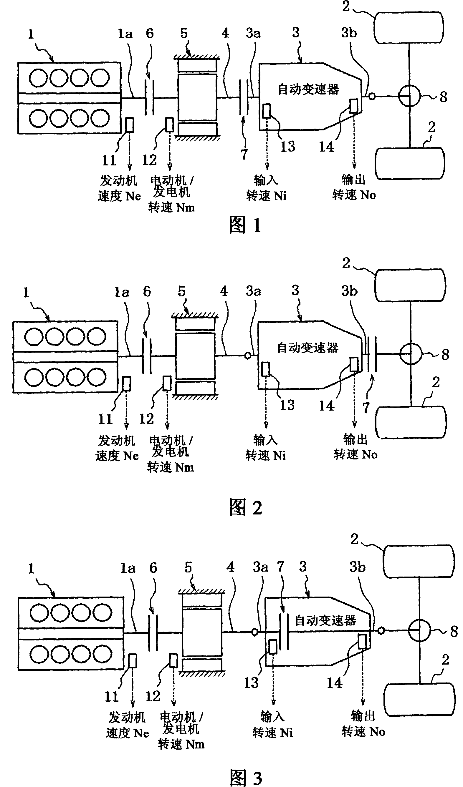
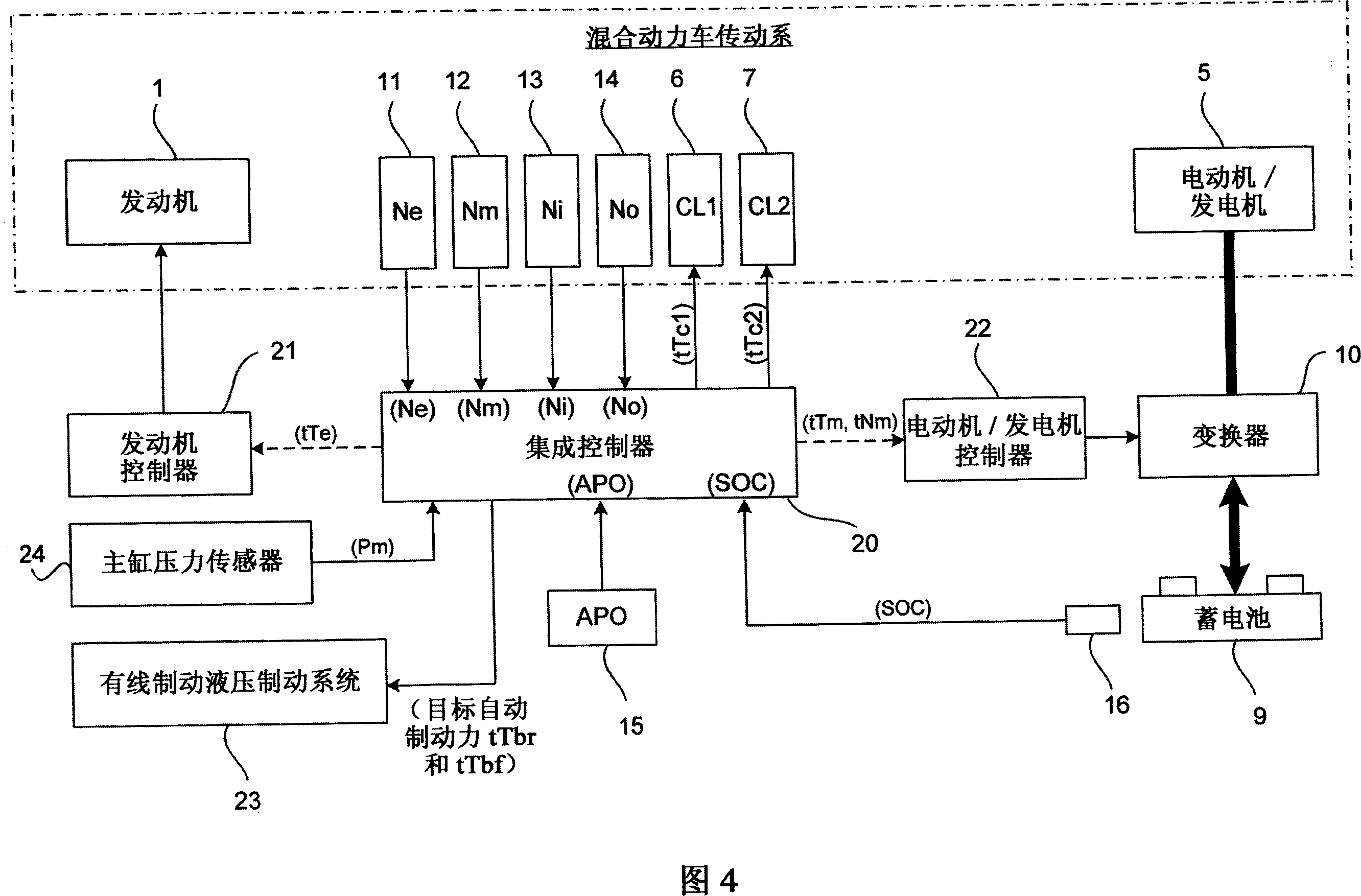
[0031]Referring to FIGS. 1 to 3 , there is illustrated a front engine / rear wheel drive vehicle (rear wheel drive hybrid vehicle) equipped with a hybrid vehicle control system according to a preferred embodiment of the present invention. Basically, the hybrid vehicles of FIGS. 1 to 3 illustrate three examples of optional drive trains of hybrid vehicles, in which the hybrid vehicle drive control system according to the present invention can be applied. Mainly, each hybrid vehicle includes, among other co...


PUM


Abstract

A hybrid vehicle control system is configured to use automatic braking to compensate for an excess or deficiency of a braking force available from the power train of a hybrid vehicle that occurs when the hybrid vehicle switches from an electric drive (EV) mode to a hybrid drive (HEV) mode when the accelerator pedal depressing amount is detected as being substantially zero. In particular, hybrid vehicle control system determines whether a power train braking force from the power train is sufficient to achieve a target braking force. If the power train braking force is sufficient to achieve the target braking force when an accelerator pedal depressing amount is detected as being substantially zero, then a wheel brake is activated to apply a wheel braking force against a wheel of the vehicle to maintain the target braking force.

Description

technical field [0001] The present invention relates to a braking control system for a hybrid vehicle having: an electric drive (EV) mode in which drive wheels are driven solely by a motor / generator; and a hybrid drive (HEV) mode in which The drive wheels are driven by the engine and the motor / generator, or by the engine alone. More particularly, the present invention relates to a braking control system for a hybrid vehicle, which is arranged to perform coasting (inertia) motion braking force control. Background technique [0002] Japanese Patent Publication No. 11-082260 discloses an example of a conventional hybrid drive system used in a conventional hybrid vehicle. Such a drive control system for a hybrid vehicle proposed in Japanese Patent Publication No. 11-082260 has a motor / generator arranged between an engine and a transmission to be combined with a shaft guiding the rotation of the engine to the transmission; with a first A clutch is disposed between the engine an...

Claims


Application Information

Patent Timeline
16 May 2007
Publication
CN1962332A
IPC
B60W10/06; B60W10/08; B60W10/18; B60W10/24; B60W20/00; B60K6/04; B60K6/48; B60K6/54; B60L7/24; B60L50/16; B60T8/17; B60W10/02; B60W10/04; B60W10/192; B60W10/196; F02D29/02
CPC
Y02T10/6286; B60W30/18109; B60W2540/10; B60W10/184; B60W10/06; B60K6/48; B60W10/02; B60L2240/486
Inventors
奥田正; 山中刚