Front and rear roller crosslinked cloth-traction mechanism for quilting machine

A technology of quilting machine and rear roller, which is applied in the direction of cloth feeding mechanism, sewing machine components, sewing machine for sewing quilts, etc. It can solve the problems affecting the quilting effect, broken threads, jumping threads, etc., so as to improve the quilting effect and solve the problem. The effect of pattern distortion

Inactive Publication Date: 2007-05-16
李德锵
View PDF0 Cites 23 Cited by
  • Summary
  • Abstract
  • Description
  • Claims
  • Application Information

AI Technical Summary

Problems solved by technology

Because the pinhole plate and the pressure roller exert a large pressure on the fabric, the fabric will inevitably be blocked if it wants

Method used


Image

  • Front and rear roller crosslinked cloth-traction mechanism for quilting machine
  • Front and rear roller crosslinked cloth-traction mechanism for quilting machine
  • Front and rear roller crosslinked cloth-traction mechanism for quilting machine

Examples


Embodiment Construction

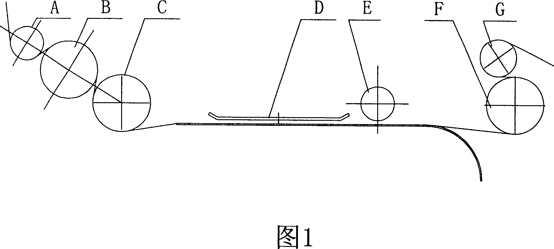
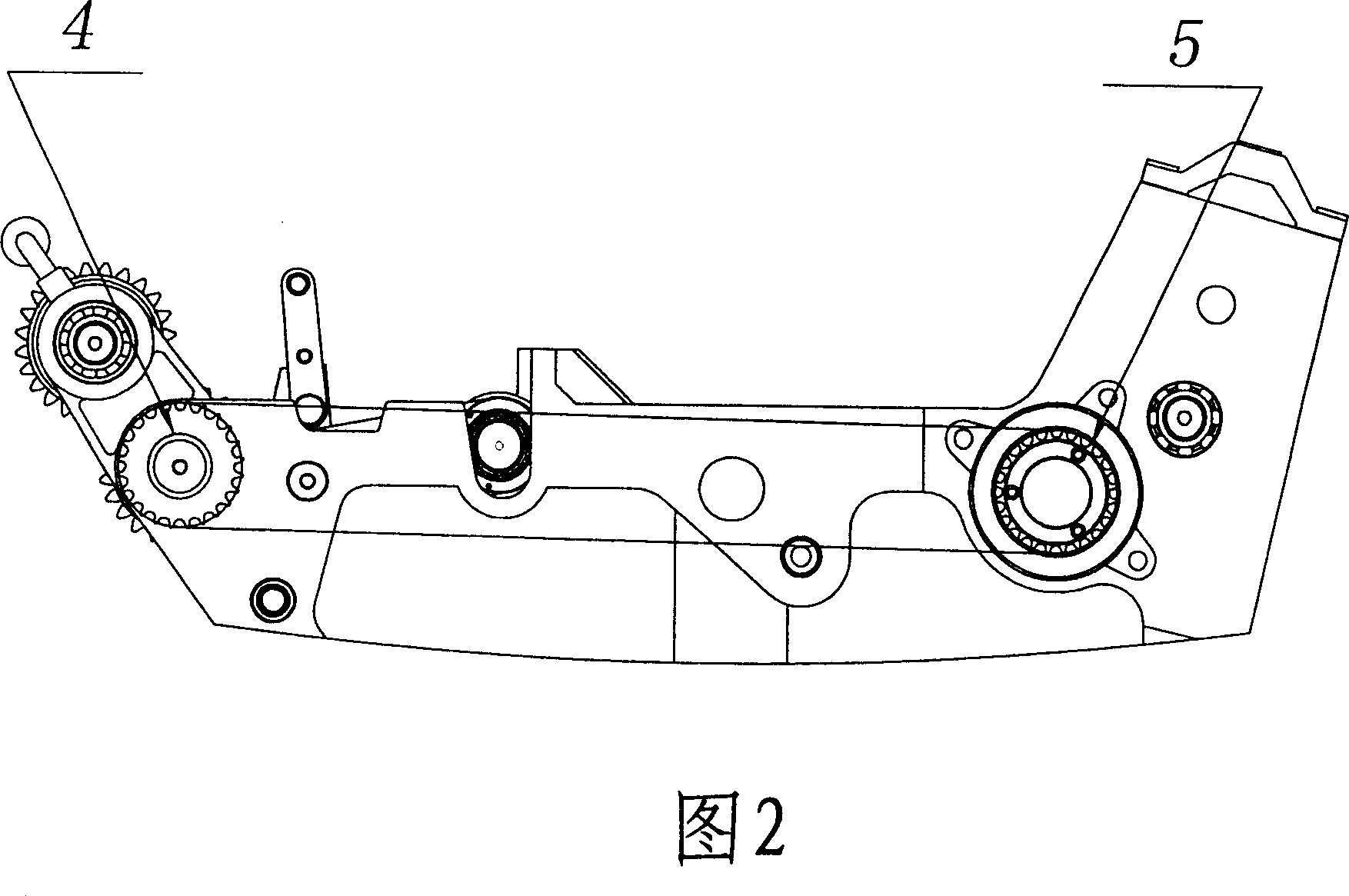
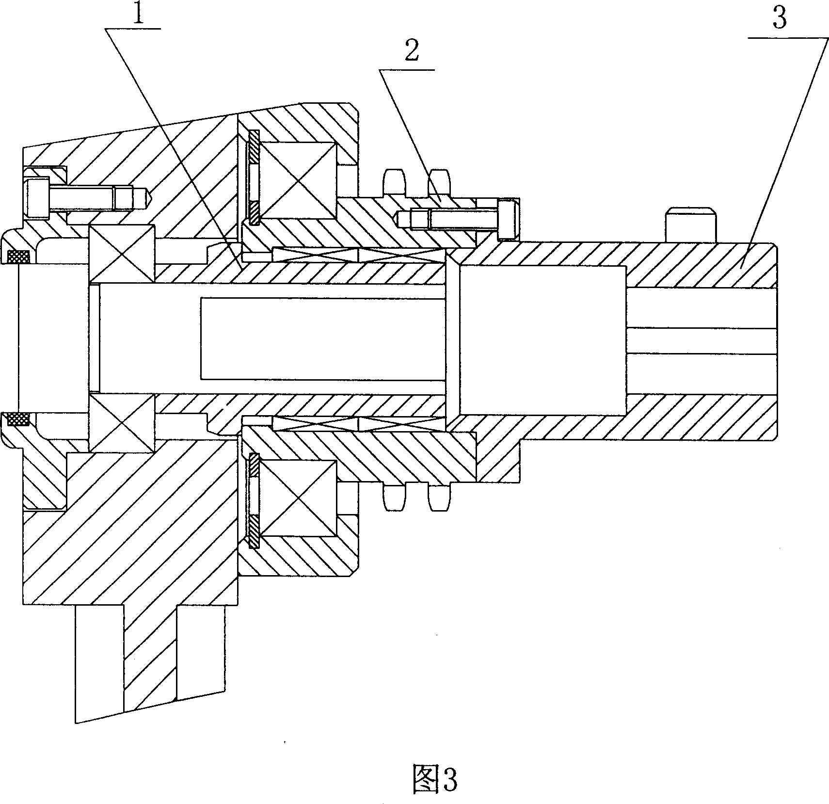
[0010] Referring to Figures 2 and 3, this embodiment has a front roller set, a rear roller set, a motor, a rolling spline, a rolling spline sleeve 3, a rear roller sprocket 2, a bearing flat hole sleeve 1. The front roller group is composed of a front main roller and a front auxiliary roller, and the rear roller group is composed of a rear main roller, a rear auxiliary roller and a rear smooth roller. The motor is a servo motor. The motor drive is connected to the input end of the rolling spline, and the auxiliary output end of the rolling spline is assembled with the rolling spline sleeve 3, the rear roller sprocket 2 and the bearing flat hole sleeve 1 in sequence. The input ends of the rear main roller and the front main roller are equipped with single The one-way rotating device 4, 5, the one-way rotating device 5 of the rear main roller is installed in the rear roller sprocket 2, and the one-way rotating device 4 of the front main roller is connected with the rear roller sproc...


PUM


Abstract

The invention discloses a cloth dragging device of quilter which front and rear rollers are interdynamic and in a union. It includes front rollers group, rear rollers group and generator; it is characterized by: it also includes rolling spline connected with and drived by generator, the sub-output ends of rolling spline are equipped with rolling splined hub (3), rear roller chain wheel (2) and the bearing flat hole sleeve (1) one by one, the input ends of the rear and front rollers are equipped with one-way rotating devices (4, 5). The invention solves the problems of pattern aberration, jumper wire and cut line leading by retardation which is the result of the cloth back in the tangential direction and improves the quilting effects.

Description

Technical field [0001] The invention relates to the field of quilting machinery, and belongs to a quilting machine front and rear rollers associated and interactive traction cloth mechanism. Background technique [0002] The quilting machine sews independent patterns, which is realized by the feeding movement in the axial direction that is the X direction and the feeding movement in the tangential direction that is the Y direction, or by the combined movement in the X and Y directions. Usually, the cloth feeding movement of the quilting machine in the Y direction is realized by the front roller group and the rear roller group relying on the friction force exerted on the cloth between the rollers to make the cloth obtain linear movement. As shown in Figure 1, the cloth pressing roller E and the pinhole plate D flatten the cloth to ensure the accuracy of the cloth movement. The front roller group of the traditional quilting machine is composed of the front main roller F and the fro...

Claims


Application Information

Patent Timeline
IPC IPC(8): D05B33/00D05B35/00D05B11/00
Inventor 李德锵
Owner 李德锵
Why Eureka
Try Eureka