Supercharge Your Innovation With Domain-Expert AI Agents!

Debug apparatus and method of computer system

A computer system and basic input technology, applied in calculation, error detection/correction, instruments, etc., can solve the problems of unable to realize debugging, unable to see error code address and data, etc., and achieve the effect of solving error code display and analysis

Inactive Publication Date: 2007-05-16
MITAC COMP (SHUN DE) LTD
View PDF1 Cites 4 Cited by
  • Summary
  • Abstract
  • Description
  • Claims
  • Application Information

AI Technical Summary

Problems solved by technology

But, when the computer system that supports PCI-Express as shown in Figure 1 starts and above-mentioned basic input / output unit 70 (being BIOS) self-inspection, there is no starting data on PCI-Express bus 100, so when computer system breaks down At that time, the debug function cannot be realized by utilizing the known device and method of the above-mentioned debug card, and the engineer cannot see the error code and address data sent by the above-mentioned basic input / output unit 70.

Method used


Image

  • Debug apparatus and method of computer system
  • Debug apparatus and method of computer system
  • Debug apparatus and method of computer system

Examples


Embodiment Construction

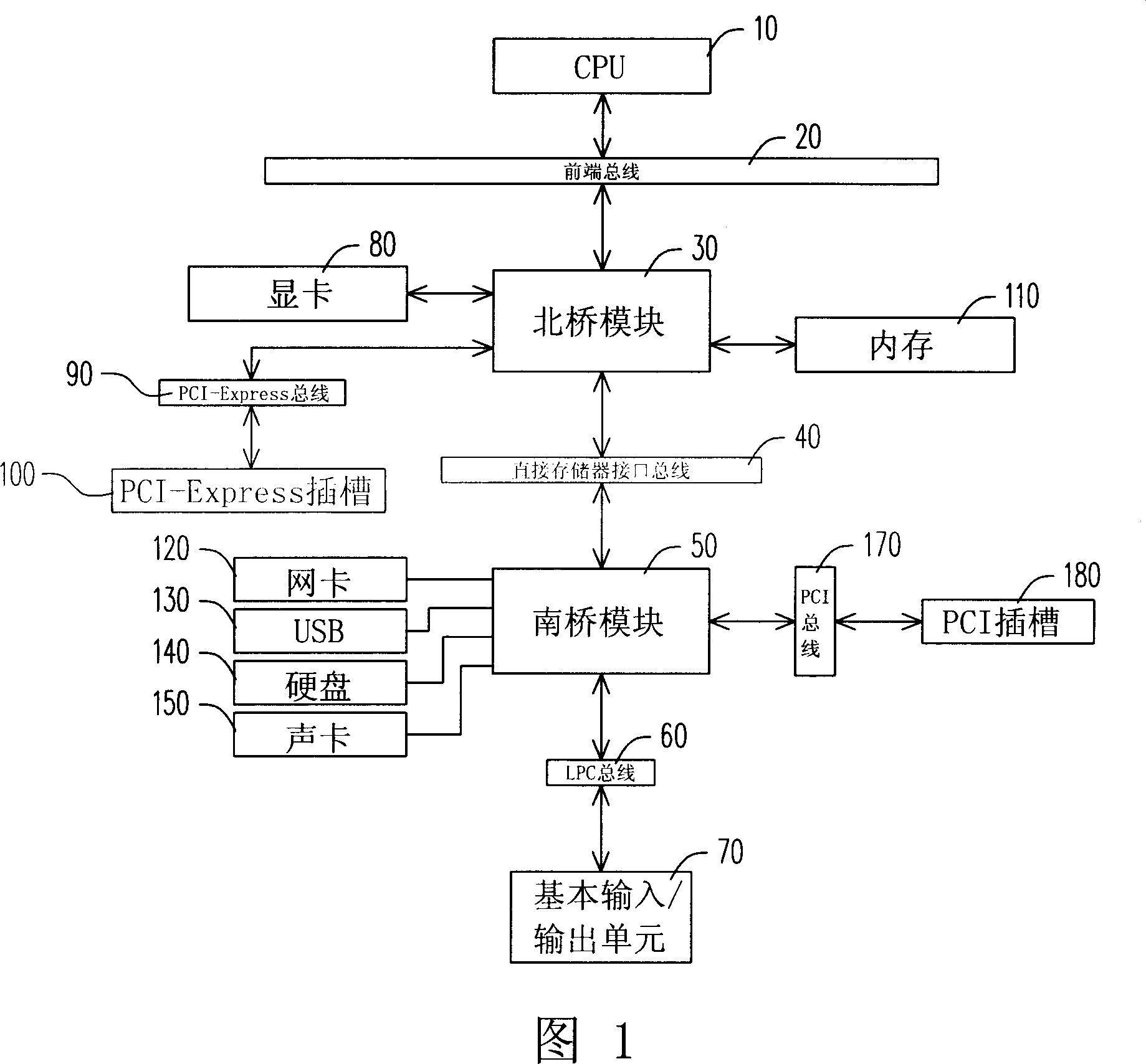
[0014] Please refer to FIG. 1 which is a structural block diagram of a widely used computer system. The above-mentioned basic input / output unit 70 (namely BIOS) is connected to the above-mentioned south bridge module 50 through the LPC bus 60, and the connection methods between other structures are as described in the background art, and will not be repeated here.

[0015] The computer system debugging device and method of the present invention are used to obtain the relevant data of the self-test of the basic input / output unit 70 when the computer system is started, so as to determine where and what kind of errors may occur in the computer system. The debugging device of the present invention is especially suitable for a computer system supporting PCI-Express, and it is connected between the basic input / output unit 70 and the south bridge module 60 through the LPC bus 60 interface.

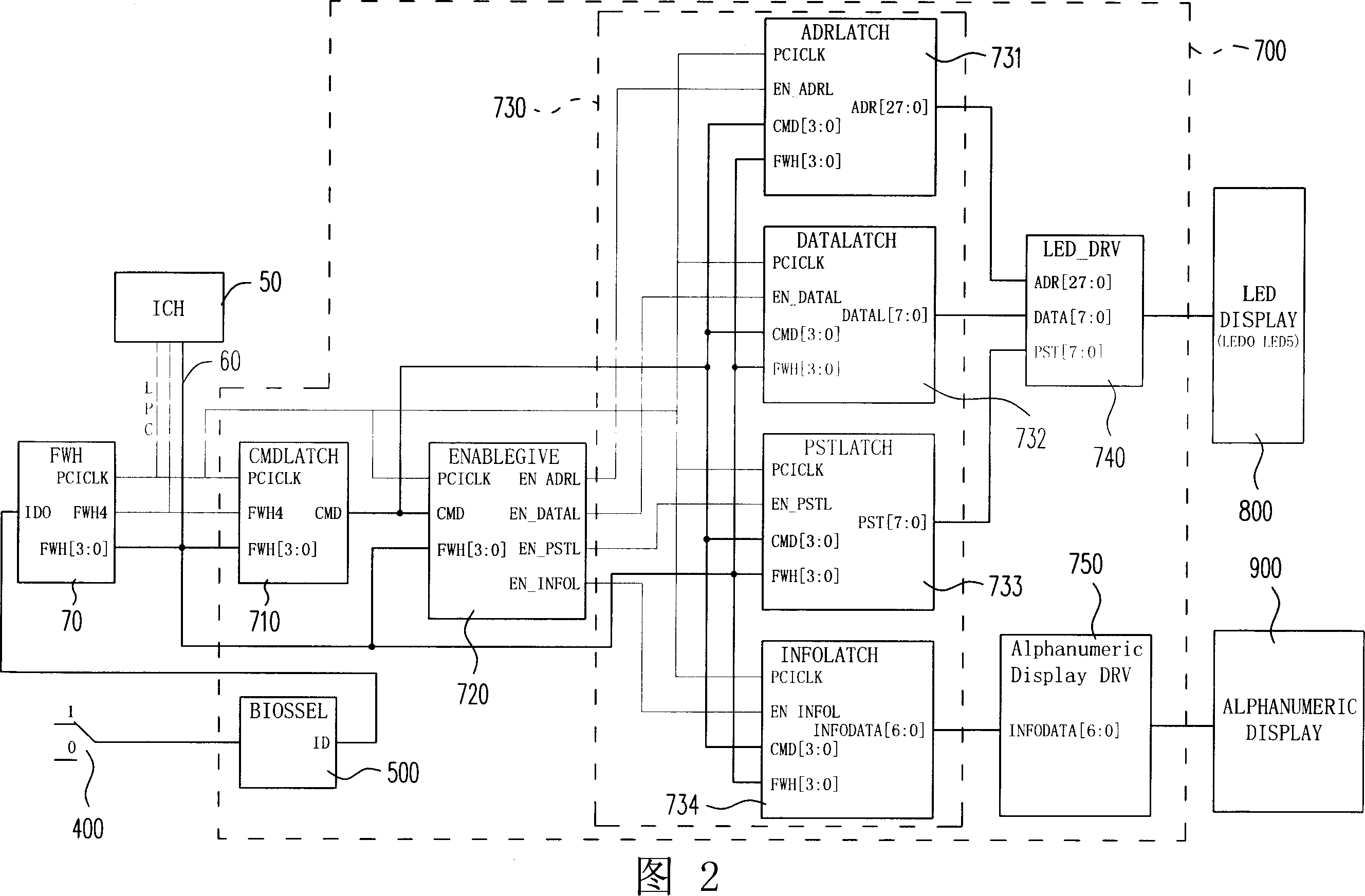
[0016] As shown in FIG. 2 , the debugging device includes: a programmable logic circuit 700 ,...


PUM


Abstract

This invention relates to computer system error removing device and its method, wherein, the device comprises programmable logic circuit and selection and control unit and display unit; the above selection control unit is connected to computer south bridge module and the selection and control unit has same basic input or output information. The programmable logic circuit comprises one order lock memory unit, one lock memory energy signal provide unit, and several lock buffer units, one display drive unit.

Description

technical field [0001] The present invention relates to a kind of debugging device, relate in particular to a kind of through the LPC (Low Ping Count) bus interface of the computer system that supports PCI-Express, be connected between the basic input / output unit and the south bridge module and the debugging device and Its debugging method. Background technique [0002] FIG. 1 shows a block diagram of a computer system widely used at present. CPU (Central Processing Unit) 10 is the core component of whole computer system, and it is connected with North Bridge module 30 by Front Side Bus (Front Side Bus, FSB) 20, and above-mentioned North Bridge module 30 is connected with South Bridge module 30 by Direct Memory Interface bus (Direct Memory Interface, DMI). The bridge module 50 is connected, and the above-mentioned south bridge module 50 is connected with the basic input / output unit 70 through the LPC (Low Ping Count) bus. Wherein, the above-mentioned north bridge module 30...

Claims


Application Information

Patent Timeline
IPC IPC(8): G06F11/00
Inventor 李杰方晓松
Owner MITAC COMP (SHUN DE) LTD
Features
  • R&D
  • Intellectual Property
  • Life Sciences
  • Materials
  • Tech Scout
  • Unparalleled Data Quality
  • Higher Quality Content
  • 60% Fewer Hallucinations
Learn More