Image processing device and method which use two images

An image processing device and image processing technology, applied in the direction of image data processing, image data processing, image analysis, etc., can solve problems such as affecting processing

Inactive Publication Date: 2007-05-16
CANON KK
View PDF4 Cites 11 Cited by
  • Summary
  • Abstract
  • Description
  • Claims
  • Application Information

AI Technical Summary

Problems solved by technology

For this reason, there are technical problem

Method used


Image

  • Image processing device and method which use two images
  • Image processing device and method which use two images
  • Image processing device and method which use two images

Examples


no. 1 example

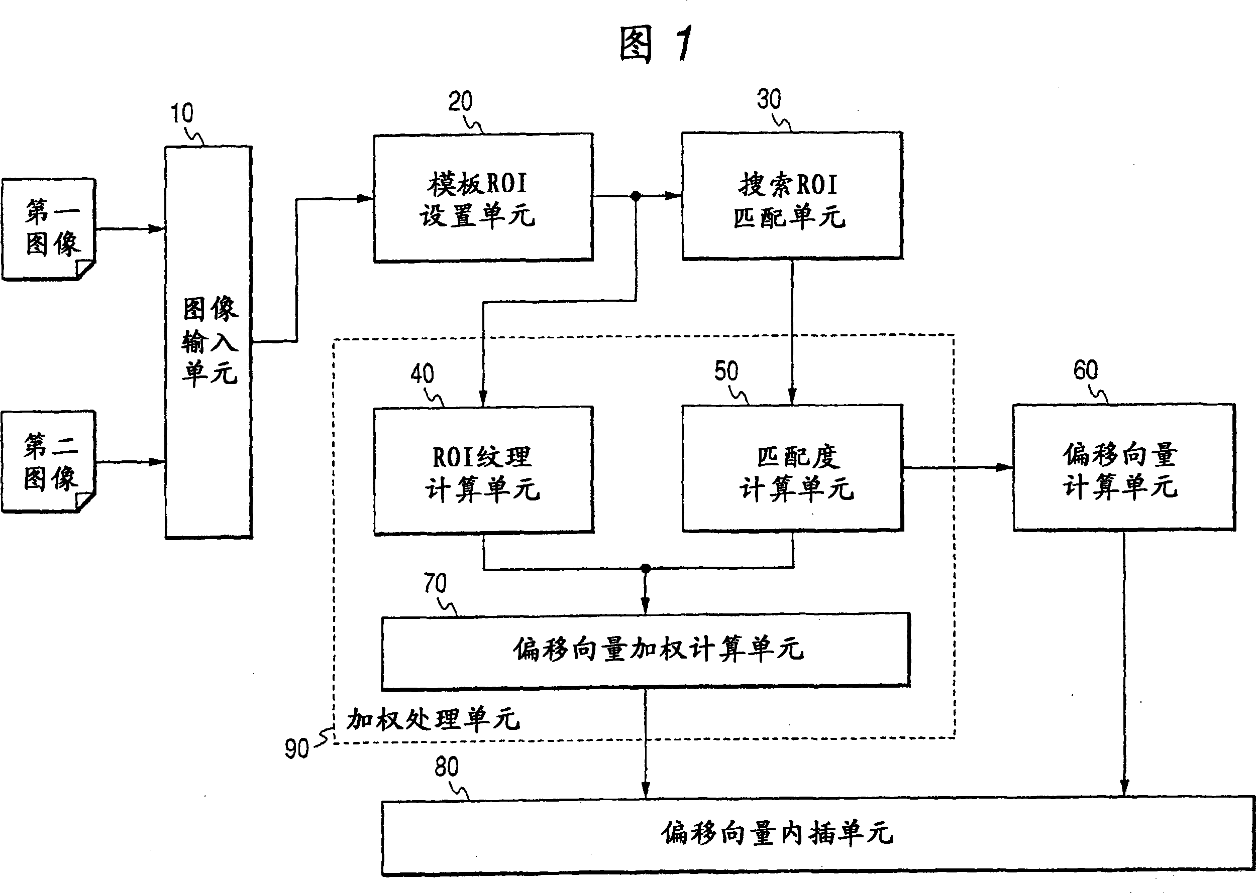
[0073] First, a first embodiment of the present invention will be described below. FIG. 1 is a functional block diagram showing the functional configuration of a medical image processing apparatus according to a first embodiment of the present invention. Incidentally, it should be noted that the medical image processing apparatus according to the present embodiment can be realized by a dedicated device realizing the functions shown in FIG. 1 or by a control program causing a general-purpose computer to execute processing described later. It should be noted, however, that each functional block shown in FIG. 1 can be realized by hardware, software, or a combination of hardware and software.

[0074] As shown in FIG. 1, the medical image processing apparatus according to the present embodiment is equipped with an image input unit 10, a template ROI (region of interest) setting unit 20, a search ROI matching unit 30, an ROI texture calculation unit 40, a matching degree calculatio...

no. 2 example

[0106] Next, a second embodiment of the present invention will be described below. In the second embodiment, it should be noted that the functional blocks are basically the same as those in the first embodiment, and only the function of the ROI texture calculation unit 40 is different from that in the first embodiment. Fig. 7 is a flowchart showing the operation of the medical image processing apparatus according to the second embodiment of the present invention.

[0107] In this embodiment, after ROI is set for the first image (step S103 ) as in the first embodiment, FFT (Fast Fourier Transform) coefficients are obtained by equation (4) (step S201 ).

[0108] F ( p , q ) = Σ m = 0 M - 1 Σ n = ...

no. 3 example

[0127]Subsequently, a third embodiment of the present invention will be described below. In the third embodiment, it should be noted that the functional blocks are basically the same as those in the first embodiment, and only the function of the ROI texture calculation unit 40 is different from those in the first and second embodiments. Fig. 8 is a flowchart showing the operation of the medical image processing apparatus according to the third embodiment of the present invention.

[0128] In this embodiment, after setting the ROI for the first image (step S103) as in the first embodiment, the horizontal Sobel operator (Sobel operator) shown in equation (8) is multiplied to the ROI, thereby calculating The horizontal edge intensity (intensity) bx(i, j) of the image at position (i, j) (step S301). Then, the vertical Subel operator as shown in equation (8) is multiplied to the ROI, thereby calculating the vertical edge strength by(i, j) of the image at position (i, j) (step S302...


PUM


Abstract

The present invention aims to provide image processing device and method capable of generating a difference image at high speed without occurring misregistration. To achieve this, in the image processing device and method, plural regions of interest are set respectively to input first and second images, a shift vector indicating a misregistration amount between the first and second images is calculated with respect to each of the regions of interest, a filter process is executed to the shift vector, the filter-processed shift vector is interpolated, the first and second images are registered based on the interpolated shift vector, and a subtraction operation is executed between corresponding pixels on the respective registered images to acquire the difference image.

Description

technical field [0001] The present invention relates to an image processing apparatus and method suitable for registration of two images that are targets of processing such as differential processing in CAD (Computer Aided Diagnosis) technology using medical images and the like. Background technique [0002] In the field of CAD, the use of digital images has grown in recent years. Therefore, by digitizing medical images, the possibility of a form of diagnosis that is difficult in conventional diagnosis using silver halide photography arises. [0003] More specifically, in conventional diagnosis, in a case where a plurality of X-ray photographs taken at different time points during observation of a patient's condition are compared for diagnosis, films on which the X-ray photographs have been separately developed are usually hung on a On the light box (schaukasten), and the hanging film is actually compared and read. [0004] Meanwhile, in the case where digital images are u...

Claims


Application Information

Patent Timeline
IPC IPC(8): A61B6/00H04N5/325G06T1/00G06T7/00
CPCG06T7/003G06T7/337
Inventor 佐藤真郭睦凌
Owner CANON KK
Why Eureka
Try Eureka