

Synthetic resin retainer and ball bearing using the same
A synthetic resin and retainer technology, which is applied to bearing components, shafts and bearings, mechanical equipment, etc., can solve the problems of bearing temperature rise, bearing life reduction, and grease deterioration, etc., to prevent the reduction of bearing life and prevent abnormalities Sound, anti-wear effect
- Summary
- Abstract
- Description
- Claims
- Application Information
AI Technical Summary
Problems solved by technology
Method used
Image

Examples
Embodiment Construction
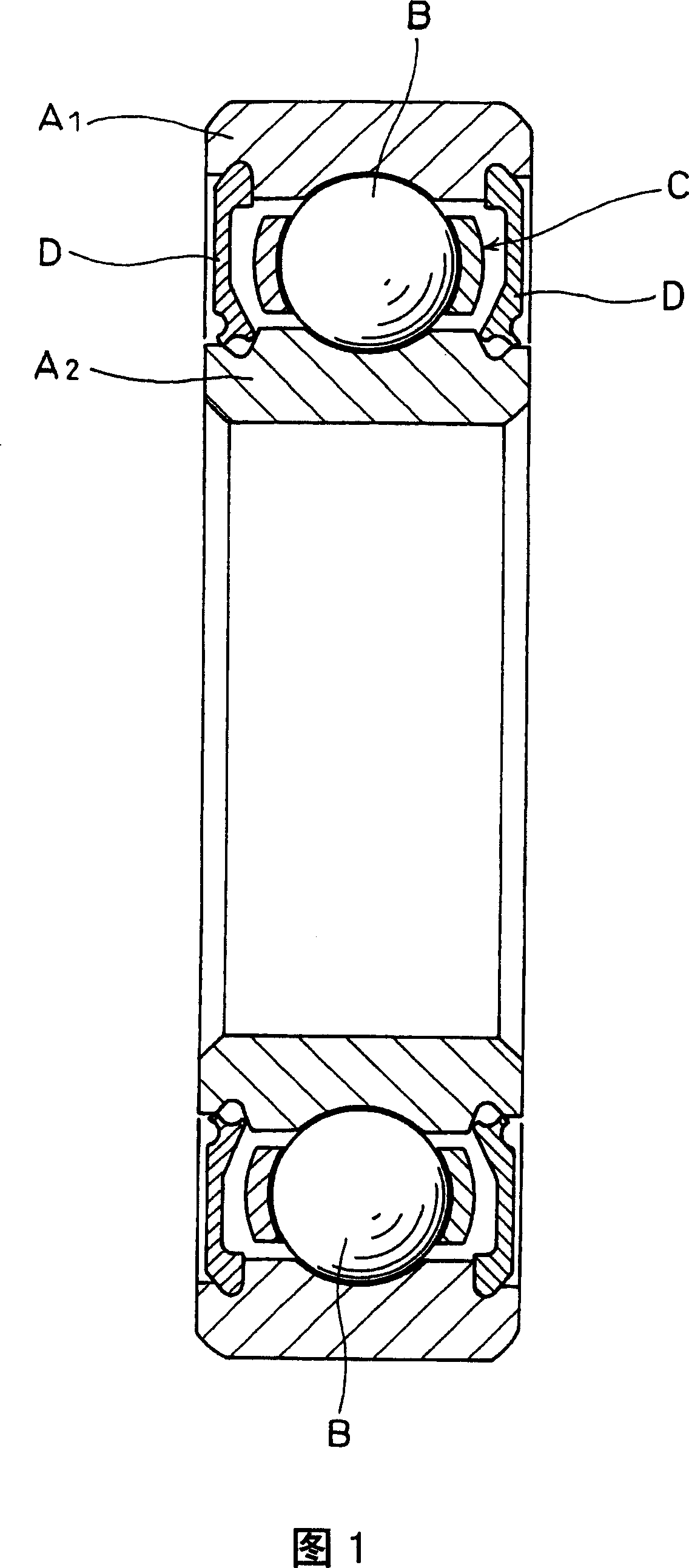
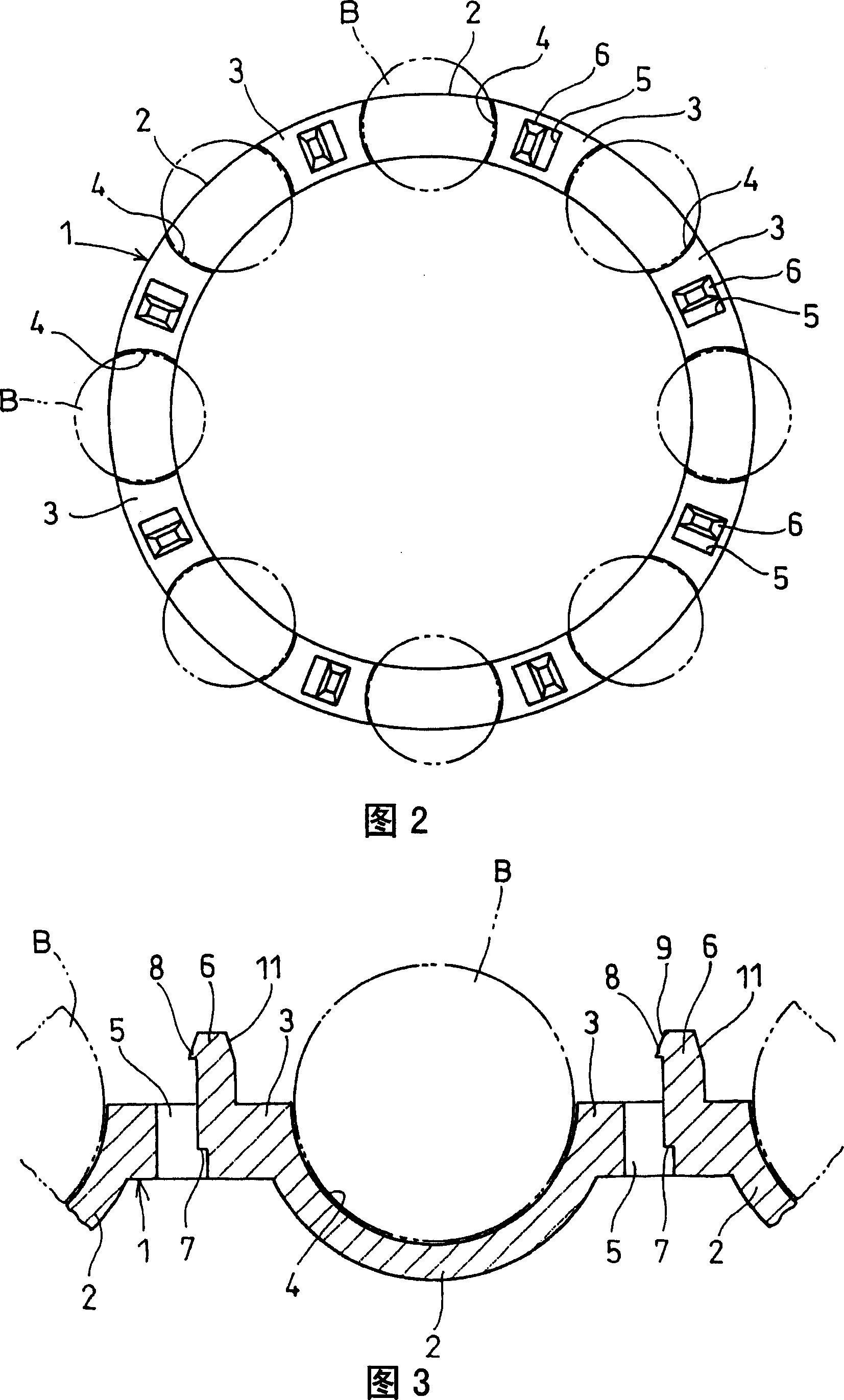
[0055] Embodiments of the present invention will be described below based on the drawings. 1 to 6 show a first embodiment of the present invention. The ball bearing has: outer ring A 1 , inner wheel A 2 , on outer wheel A 2 and inner wheel A 2 A plurality of balls B assembled between them, and a cage C that holds the balls B. As shown in FIGS. 3 to 5 , the cage C is composed of two ring-shaped bodies 1 , 1 , and each ring-shaped body 1 is formed into the same shape by molding a synthetic resin. In addition, on outer wheel A 1 and inner wheel A 2 As shown in Figure 1, the annular space formed between them is sealed with a bearing gasket D and filled with grease.
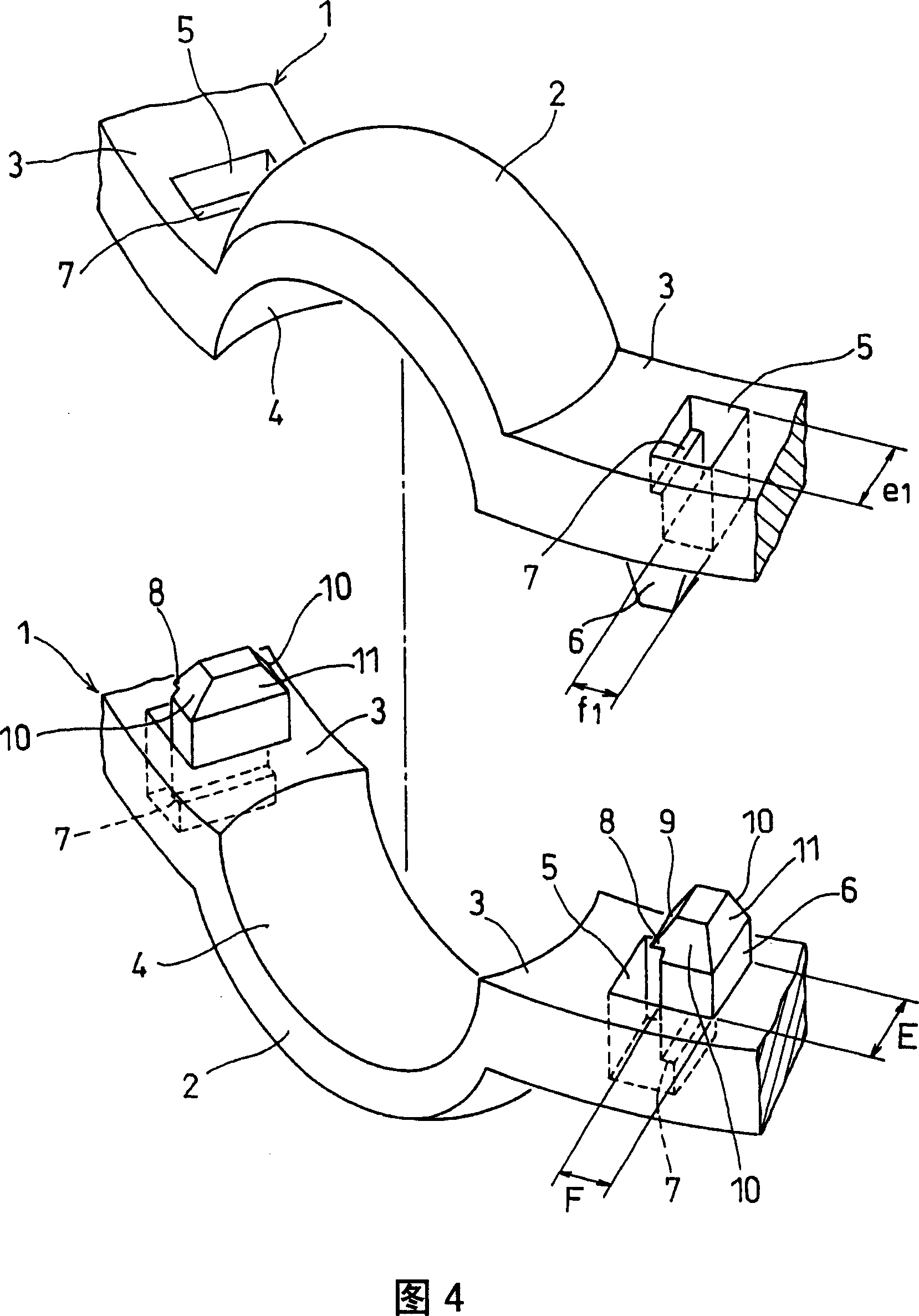
[0056] As shown in FIGS. 2 to 4 , the annular body 1 has a plurality of hemispherical ball holding portions 2 and a plurality of plate-shaped coupling portions 3, and the above-mentioned ball holding portions 2 and coupling portions 3 are formed alternately in the circumferential direction, and each The ball h...
PUM
 Abstract
Description
Claims
Application Information