

Structure for lock cylinder
A technology of lock cylinder and side pin, which is applied in building locks, cylinder pin locks, building structures, etc. It can solve the problems of unsmooth insertion and removal of angle keys and reduce processing difficulty, so as to reduce production cost, reduce processing difficulty, The effect of reducing friction
- Summary
- Abstract
- Description
- Claims
- Application Information
AI Technical Summary
Problems solved by technology
Method used
Image

Examples
Embodiment 1
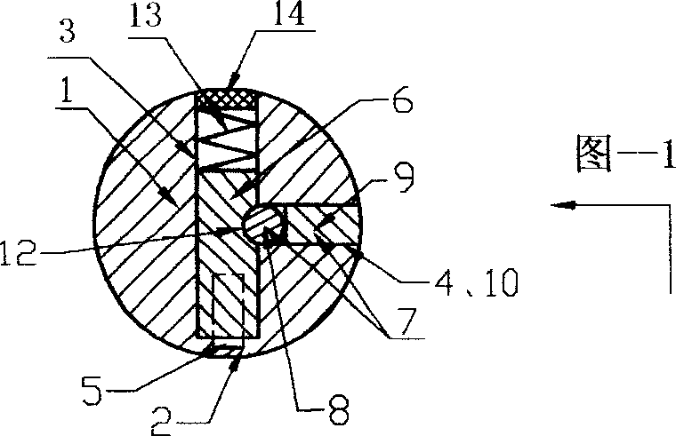
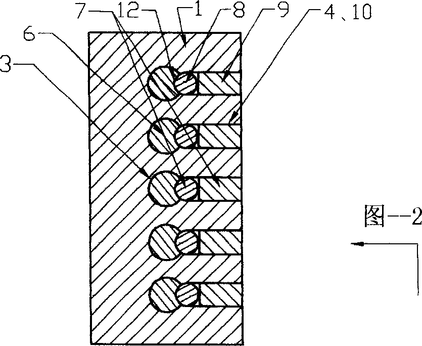
[0025] Embodiment 1: On the basis of the basic structure of the lock cylinder, the side pin holes 4 are divided into a row of five round holes, each hole has a small ball pin 8 and a cylindrical lock bolt 9, and the angle pins in each pin hole 3 All have a spring 13, sealing piece 14 on 6, and this lock core is in unlocked state (as shown in Figure 1, Figure 2).
Embodiment 2
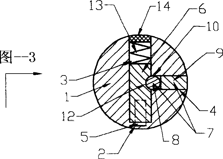
[0026] Embodiment 2: On the basis of the basic structure of the lock cylinder, the side pinholes 4 are divided into a row of five small pinholes 10 and a bar-shaped groove, and each small pinhole 10 has a small ball pin 8 and a bar-shaped groove. A strip lock bolt 9 is arranged in the inside, and a spring 13 and a sealing piece 14 are all arranged on the angle pins 6 in each pin hole 3, and the lock is in an unlocked state (as shown in Fig. 3 and Fig. 4).
Embodiment 3
[0027] Embodiment 3: On the basis of the basic structure of the lock core, the side pinhole 4 is a strip-shaped groove, and a strip-shaped lock bolt 9 is built in the groove, and a row of five small pinhole holes 10 are opened in the lockbolt 9, and each hole All have the small marble 8 of a head circular arc, and this lock core is an idling lock core (as shown in Figure 5 and Figure 6) that is in the unlocked state.
PUM
 Abstract
Description
Claims
Application Information