Wind-energy compressor using wind energy to compress air

A technology for compressing gas and heaters, applied in the field of wind energy heaters, which can solve the problems of insufficient utilization of wind energy, environmental pollution, and high cost, and achieve the effects of high wind energy utilization efficiency, cost reduction, and no environmental pollution

Inactive Publication Date: 2007-05-23
田振国
View PDF0 Cites 37 Cited by
  • Summary
  • Abstract
  • Description
  • Claims
  • Application Information

AI Technical Summary

Problems solved by technology

[0003] In order to overcome the shortcomings of some wind energy heating devices that cannot make full use of wind energy, high cost a

Method used


Image

  • Wind-energy compressor using wind energy to compress air
  • Wind-energy compressor using wind energy to compress air
  • Wind-energy compressor using wind energy to compress air

Examples


Embodiment 1

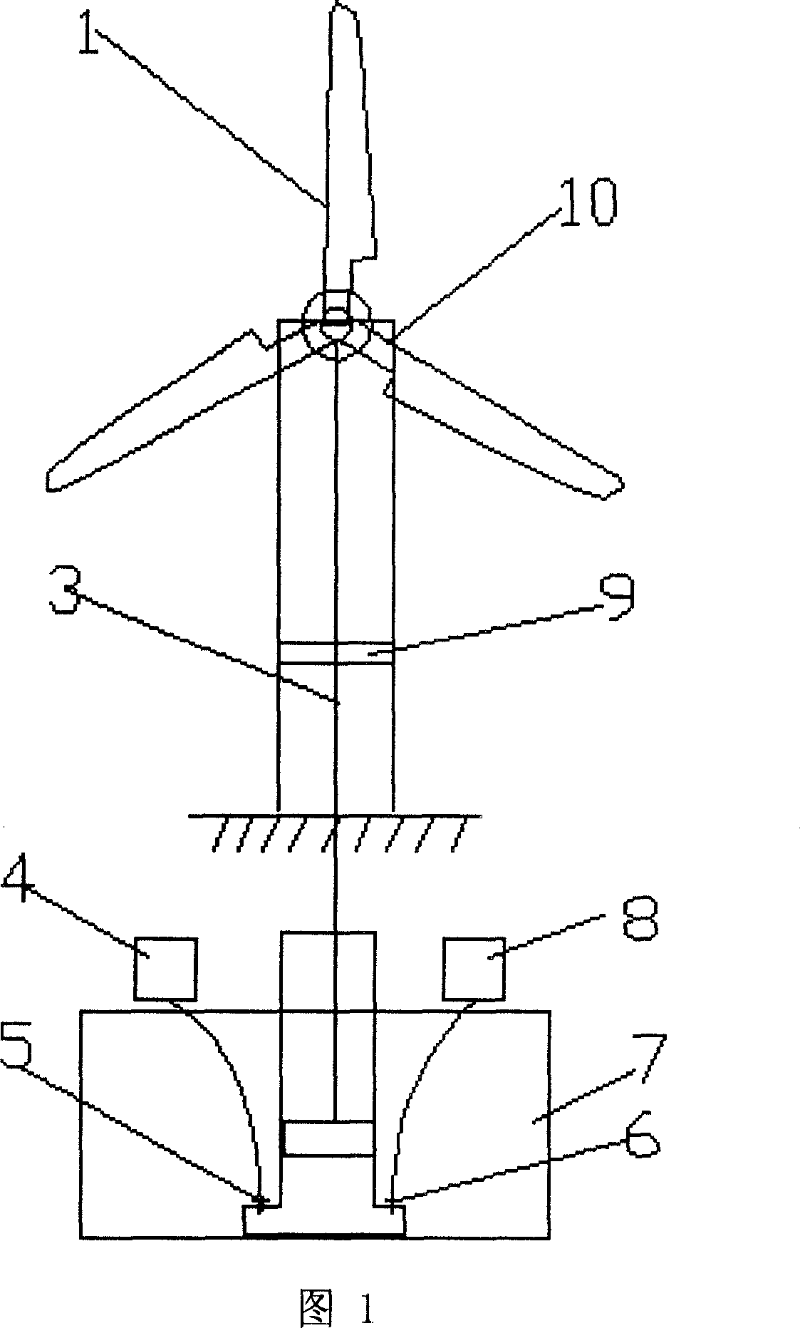
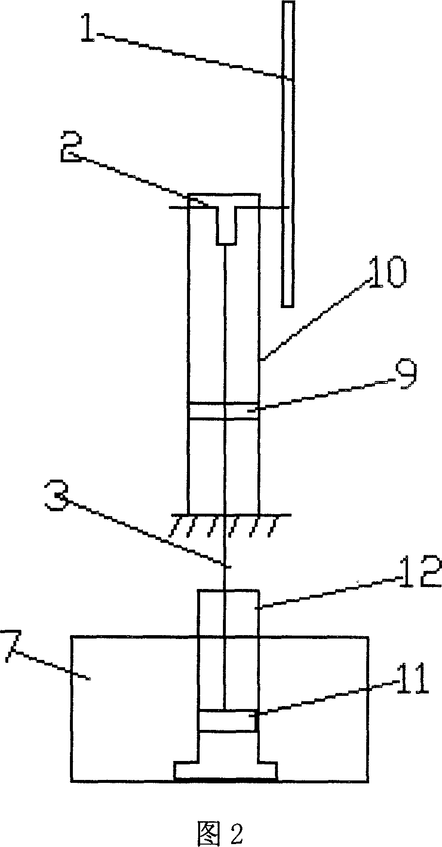
[0013] See Figure 1 and Figure 2. In the figure: 1. wind wheel, 2. crankshaft, 3. connecting rod, 4. pressure tank, 5. exhaust valve, 6:. intake valve, 7. water tank, 8. pressure tank, 9. turntable, 10. Tower frame, 11. piston, 12. cylinder.

[0014] The wind wheel 1 and the crankshaft 2 are connected together, and the crankshaft 2 is fixed on the upper end of the tower 10 . The piston 11 is connected with the crankshaft 2 through the connecting rod 3, reciprocates in the cylinder 12 as the crankshaft 2 rotates, compresses the gas in the cylinder 12 to do work, and converts mechanical energy into heat energy. Heat energy is conducted to the water tank for collecting heat energy through the cylinder, and the water tank is connected with the indoor heating device or the hot water storage. The exhaust valve 5 is installed on the cylinder 12. When the temperature of the gas in the cylinder 12 is too high and the pressure is too high, the valve opens to discharge a certain amount...

Embodiment 2

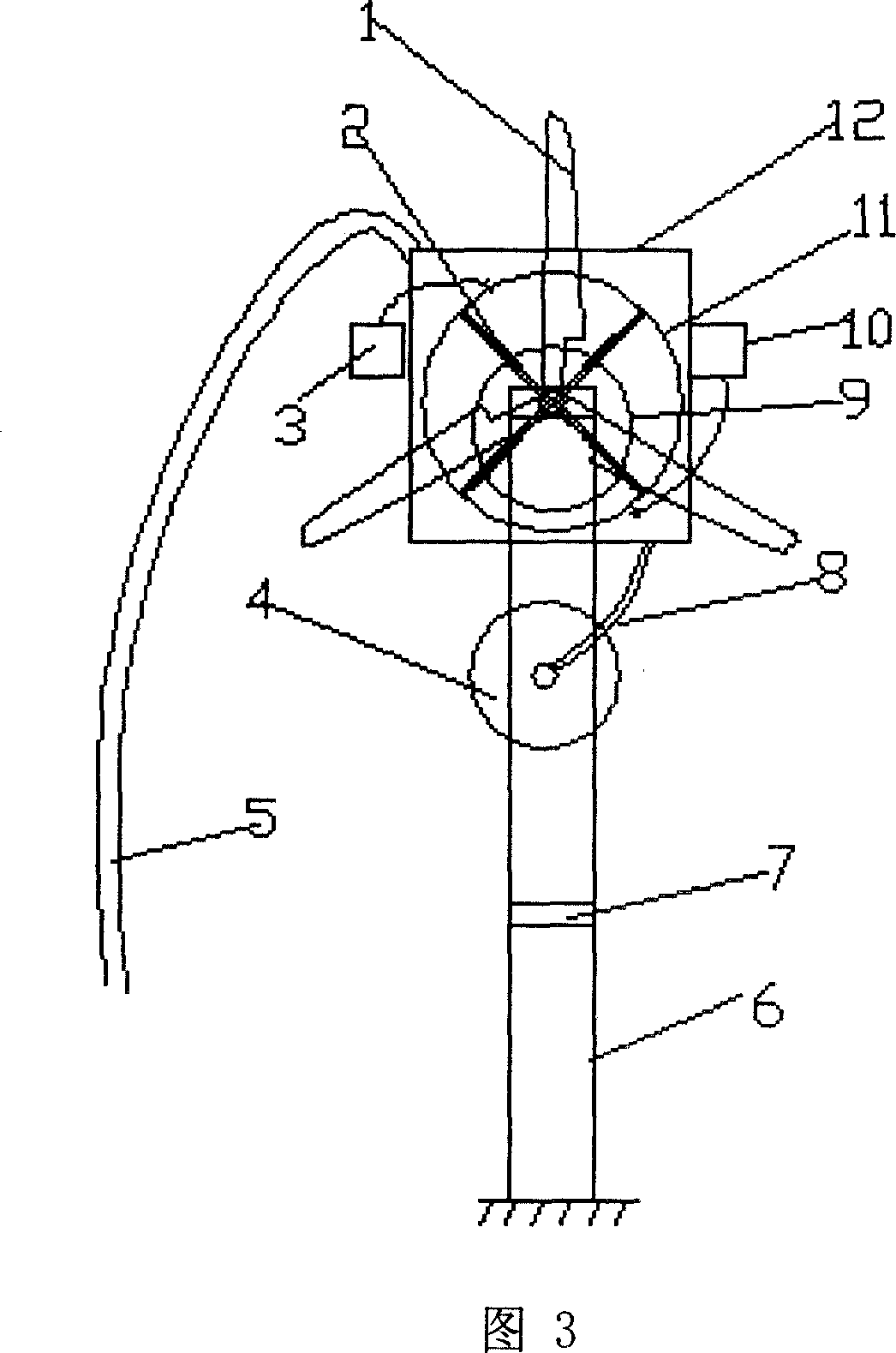
[0016] See Figure 3 and Figure 4. In the figure: 1. Wind wheel, 2. Slider, 3. Pressure tank, 4. Air collector, 5. Air duct, 6. Tower, 7. Turntable, 8. Air duct, 9. Rotor, 10. Pressure tank , 11. Stator, 12. Collector, 13. Main shaft.

[0017] The wind wheel 1 and the rotor 9 are connected together through a main shaft 13, and both ends of the main shaft 13 are fixed on the heat collector 12 with bearings. The rotor 9 is installed eccentrically on the stator 11. When the rotor 9 rotates, the slides 2 are pressed against the inner wall of the stator 11 under the action of centrifugal force, and the space between two adjacent slides 2 changes continuously during the rotation. Compressed gas does work, converting mechanical energy into heat. The stator 11 conducts heat energy to the air in the heat collector 12, and the heat collector 12 is fixed on the tower, and the lower part is effectively connected with a funnel-shaped wind collector 4 through the air pipe 8, and the wind e...


PUM


Abstract

It relates to a wind energy heater using wind energy compressing gases. It has a pylon bench with a fixed windwheel, a compressor joint for windwheel and compressed gases. The compressor can change mechanical energy into heat through compressing of gases. Twp pressure tanks connect with intake and outlet valves of the compressor to adjust the air pressure inside the compressor. The pylon bench is divided into top and down parts, with a middle rotating table and the top of the pylon bench also being able to rotate. It can be used for indoor heating and hot water supply.

Description

technical field [0001] The invention relates to a wind energy heater which utilizes wind energy to compress gas to do work and convert wind energy into heat energy. Background technique [0002] At present, the device utilizing wind energy heating mainly converts wind energy into electrical energy through a wind generator, and then utilizes electric heaters to heat to provide thermal energy. This kind of heater has an intermediate process of electric energy conversion, which reduces the efficiency of wind energy utilization; at the same time, an electric energy storage device needs to be added, and the existing electric energy storage technology is relatively expensive, and some also pollute the environment. Contents of the invention [0003] In order to overcome the deficiencies of some wind energy heating devices that cannot make full use of wind energy, high cost and environmental pollution, the present invention provides a compressed wind energy heater that converts wi...

Claims


Application Information

Patent Timeline
IPC IPC(8): F24J3/00
Inventor 李治国田振国
Owner 田振国
Why Eureka
Try Eureka