

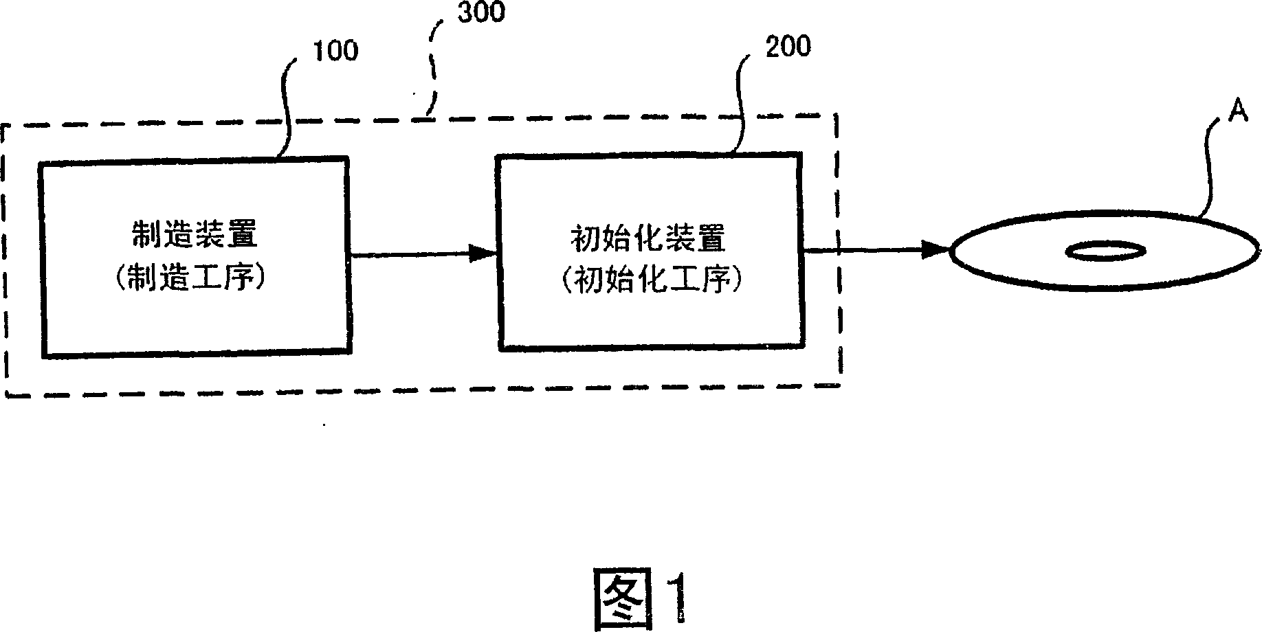
Optical recording method, optical recording apparatus and optical storage medium
An optical recording medium and recording line technology, applied in optical recording/reproducing/erasing methods, optical recording heads, optical recording systems, etc., can solve the problem of difficult to fully ensure rewriting characteristics, large erasing power Peh, difficult to fully ensure Issues such as first recording features or overwriting features
- Summary
- Abstract
- Description
- Claims
- Application Information
AI Technical Summary
Problems solved by technology
Method used
Image

Examples
Embodiment A-1
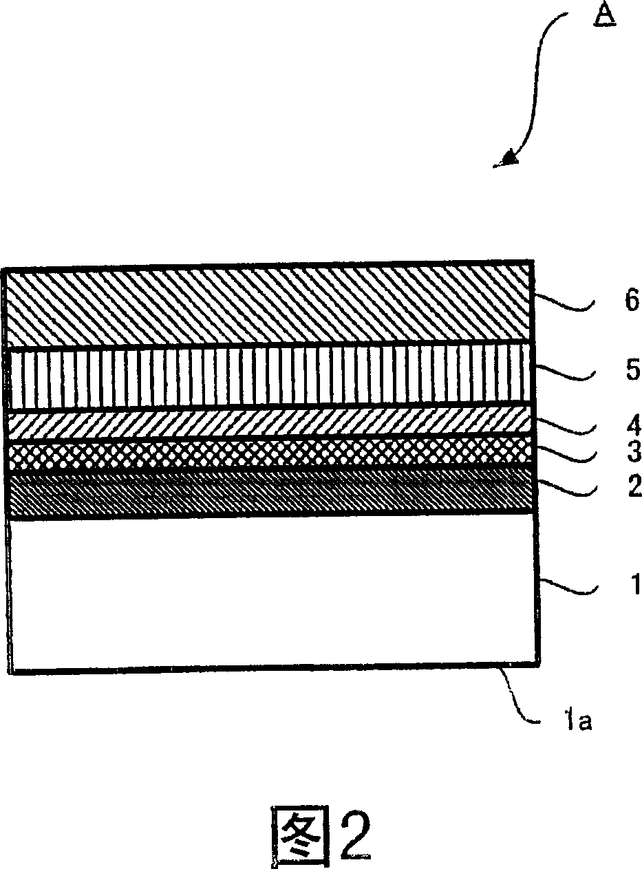
[0142] On a substrate 1 made of polycarbonate resin with a diameter of 120 mm and a plate thickness of 0.6 mm, various layers described below were formed. Grooves were formed on the substrate 1 with a channel pitch of 0.74 μm. The groove depth is 25 mm, and the ratio of the groove width to the land width is about 40:60. Among them, the groove is convex when viewed from the incident direction of the recording / reproducing or erasing laser light.
[0143] First, exhaust the vacuum container to 3×10 -4 After pa, at 2×10 -1 In the argon atmosphere of Pa, 20mol% SiO was added 2The first protective layer 2 with a layer thickness of 70 nm was formed on the substrate 1 by a high-frequency magnetron sputtering method using a ZnS target.
[0144] Next, a recording layer 3 with a layer thickness of 16 nm was sequentially laminated using a four-element single alloy target of Ge-In-Sb-Te, and then a second protective layer with a layer thickness of 16 nm was laminated using the same mat...
Embodiment A-2
[0155] Using the same optical recording medium A as in Example A-1, recording and evaluation were performed under the same conditions as in Example A-1 except that the erasing power Pe was changed to 3.8 [mW]. R0 was 17.4, and R1 after irradiating a laser with erasing power Pe=3.8 [mW] once was 17.5 (R1 / R0=1.006).
[0156] The initial characteristics and overwrite recording characteristics are shown in Table 1. The jitter of DOW0 is 6.8%, the jitter of DOW1 is 8.6%, and the jitter of DOW9 is 7.9%. In addition, although not described, DOW10000 has a jitter of 9.2%, and the characteristics are always stable even after rewriting, and the recording characteristics are as good as in Example A-1.
Embodiment A-3
[0158] Using the same optical recording medium A as in Example A-1, recording and evaluation were performed under the same conditions as in Example A-1 except that the erasing power Pe was changed to 5.6 [mW]. R0 was 17.4, and R1 after irradiating laser light with erasing power Pe=5.6 [mW] once was 17.9 (R1 / R0=1.029).
[0159] The initial characteristics and overwrite recording characteristics are shown in Table 1. DOW0 jitter is 7.0%, DOW1 jitter is 8.7%, and DOW9 jitter is 8.4%. In addition, although not described, the jitter of DOW10000 was 9.5%, and the characteristics were always stable even after rewriting, and the recording characteristics were as good as in Example A-1.
PUM
| Property | Measurement | Unit |
|---|---|---|
| thickness | aaaaa | aaaaa |
| reflectance | aaaaa | aaaaa |
| reflectance | aaaaa | aaaaa |
Abstract
Description
Claims
Application Information