Electrostatic dust catcher

A collector and floating dust technology, applied in the direction of external electrostatic separator, electrostatic separation, electrode structure, etc., can solve the problems of polluting surrounding objects and difficult cleaning

Inactive Publication Date: 2007-05-30
陈鑑波
View PDF0 Cites 6 Cited by
  • Summary
  • Abstract
  • Description
  • Claims
  • Application Information

AI Technical Summary

Problems solved by technology

However, this patent has no intention to concentrate and settle the floating dust to the specified place
The disadvantage of its structure is naturally that the floating dust settles everywhere and pollutes the surrounding objects.
and not easy to clean

Method used


Image

  • Electrostatic dust catcher
  • Electrostatic dust catcher
  • Electrostatic dust catcher

Examples


Embodiment Construction

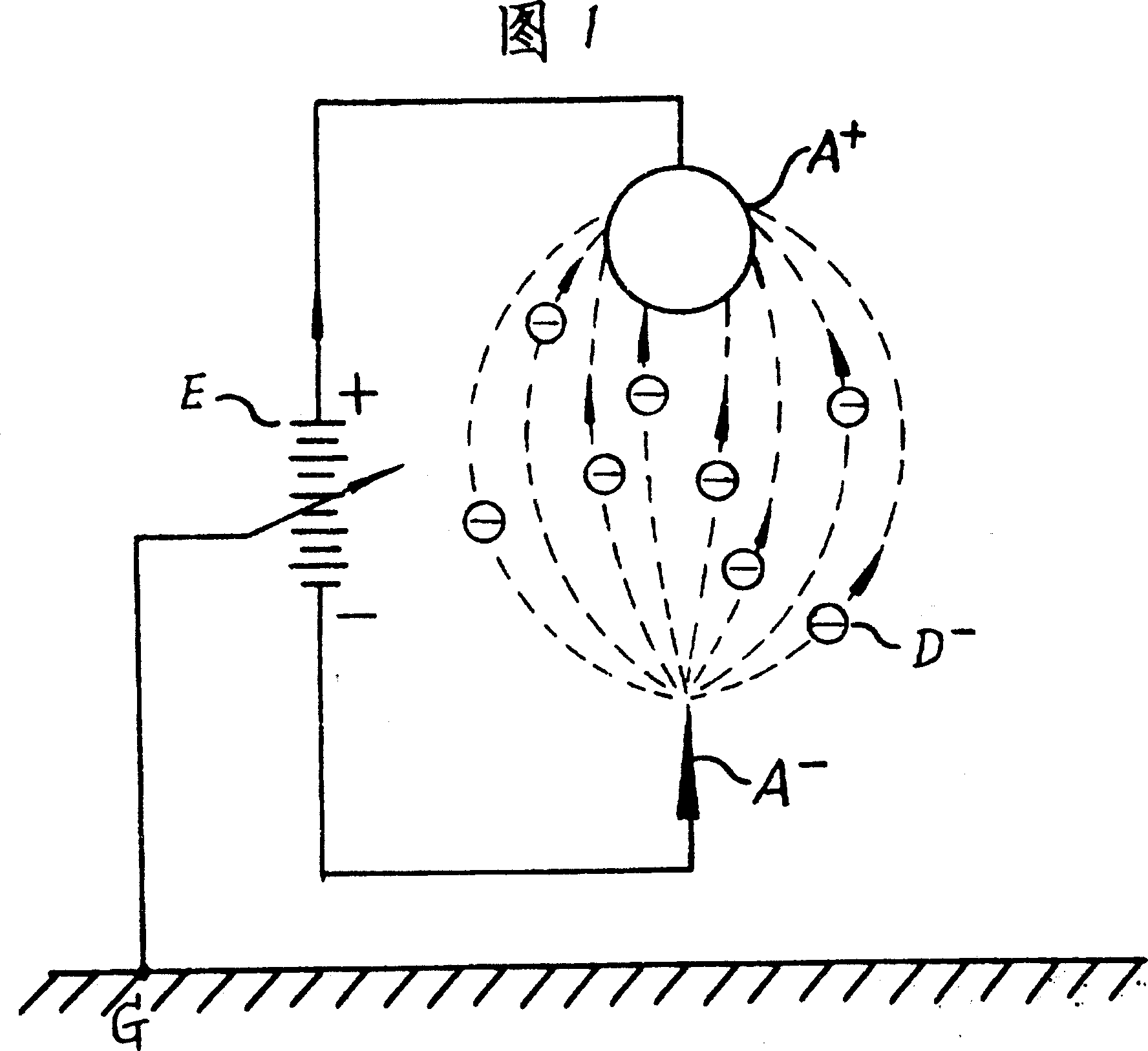
[0004] Fig. 1 is the specific device of the electrostatic floating dust collector proposed according to the present invention;

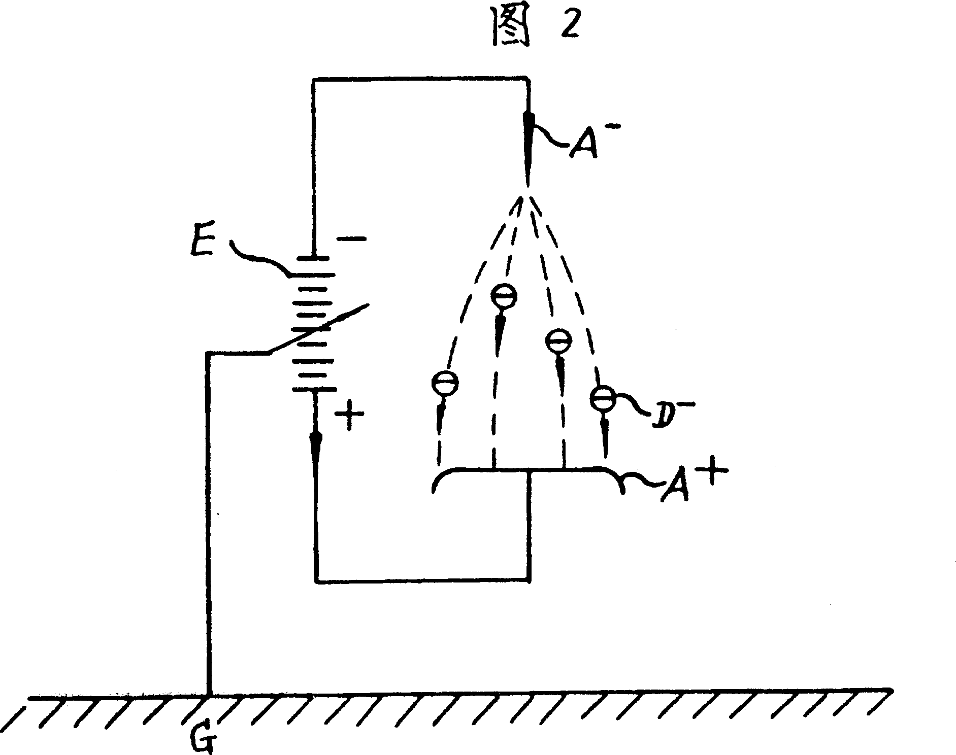
[0005] What Fig. 2 illustrates is another specific device of the present invention;

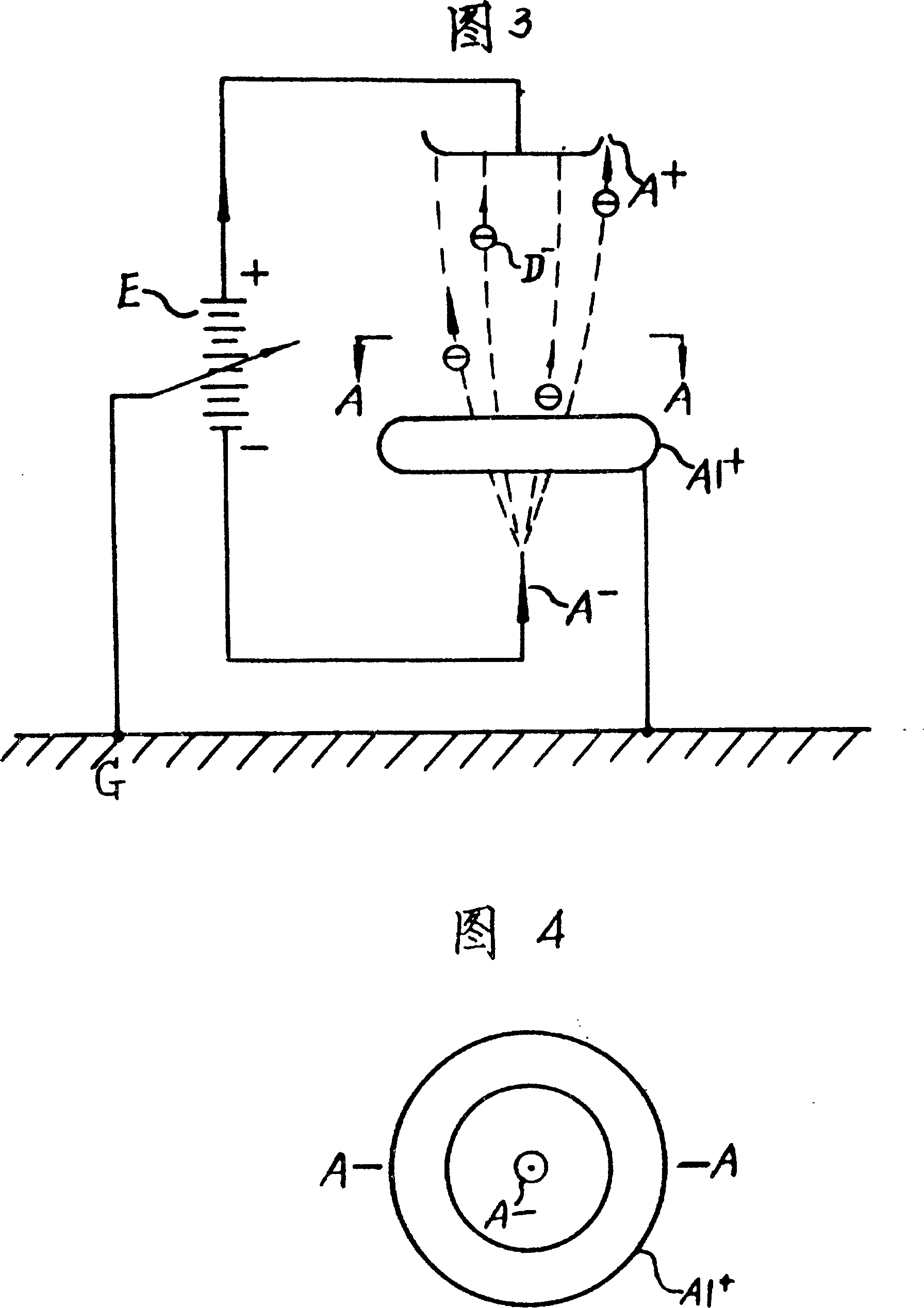
[0006] Figure 3 illustrates a further arrangement with a fly ash collector consisting of ring electrodes concentric with the negative ion generator.

[0007] What Fig. 4 shows is the top view of Fig. 3 .

[0008] The dotted line in each figure above represents the possible path when the negatively charged floating dust is displaced to the dust collecting pole.

[0009] In the device shown in Figure 1, the dust collecting pole A+ has a relatively large radius of curvature, and is connected to the negative ion generator A- through a high-voltage DC power supply E. The positive pole of the power supply is connected to the dust collector A+, and the negative pole is connected to the negative ion generator A-. The grounding point of the power supply is indicated by G i...


PUM


Abstract

It is an air purifier using electrostatic collecting and depositing floating dusts. It is made of at least of two electrodes, with one side a dust collector opposite to the land and surrounding articles with certain positive electrical potential, the other side a negative ion generator, with electrostatic field between them, electric line of force pointing to the negative ion generator from the dust collector. Negative ion makes the floating dust having negative charges, having the flowing dust accumulating and depositing to the dust collector through the attraction of the electrostatic field.

Description

technical field [0001] The invention relates to a new device for purifying air by utilizing an electrostatic field to make floating dust directional and concentrated to settle. Background technique [0002] People have known for a long time the technology of utilizing negative air ionizers to purify the air. For example, the negative ion generator proposed by the international patent application PAJNQ401156 aims to use negative ions to capture floating dust and purify the air. Yet this patent has no intention to make the floating dust concentrate and settle to the prescribed occasion. The shortcoming of its structure is naturally that the floating dust arbitrarily settles everywhere, polluting the surrounding objects. And not easy to clean. Contents of the invention [0003] The purpose of the present invention is to provide a device capable of concentrating and precipitating the floating dust. The two do not have the disadvantages described above, and it is convenient...

Claims


Application Information

Patent Timeline
Patent Type & Authority Applications(China)
IPC IPC(8): B03C3/04B03C3/45
Inventor 陈鑑波
Owner 陈鑑波
Why Eureka
Try Eureka