Fast regulating floor supporting device

A technology for supporting devices and floors, applied in the directions of floors, buildings, building structures, etc., can solve problems such as troublesome laying, and achieve the effects of convenient height adjustment, simple structure and low production cost

Inactive Publication Date: 2007-06-06
黄磊
View PDF0 Cites 3 Cited by
  • Summary
  • Abstract
  • Description
  • Claims
  • Application Information

AI Technical Summary

Problems solved by technology

[0003] The technical problem to be solved by the present invention is to provide a quick-adjustable floor support device, which overcomes the inconvenience of laying when the existing floor support device is used as a support for raised wooden floors

Method used


Image

  • Fast regulating floor supporting device

Examples


Embodiment Construction

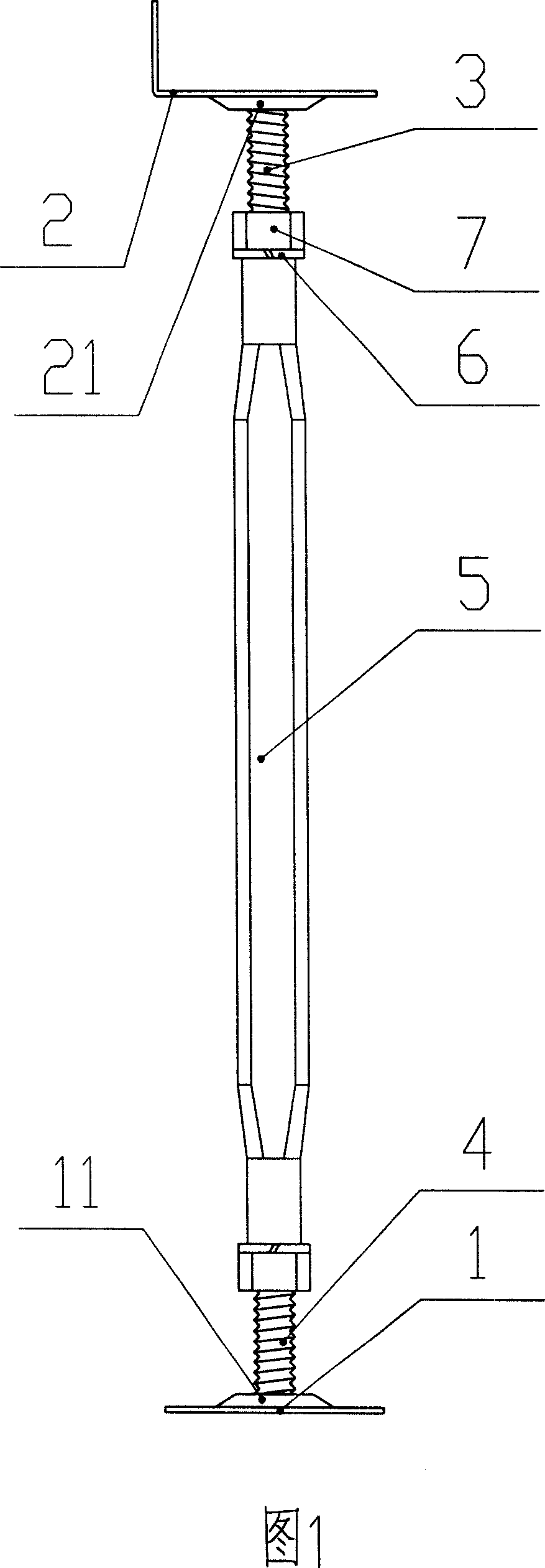
[0010] As shown in Figure 1, the quick-adjustable floor support device of the present invention includes a base plate 1, a top plate 2, an upper tooth bar 3, a lower tooth bar 4, and a joint column 5 with internal threads at both ends, and the center of the bottom plate 1 is provided with a bottom plate boss. 11. The center of the bottom plate boss 11 is provided with a connecting hole of the lower tooth bar, the lower tooth bar 4 passes through the lower tooth bar connecting hole, the end of the lower tooth bar 4 is welded to the bottom plate 1, and the center of the top plate 2 is provided with a top plate boss 21, the top plate The center of the boss 21 is provided with an upper tooth bar connecting hole, the upper tooth bar 3 passes through the upper tooth bar connecting hole, the end of the upper tooth bar 3 is welded to the top plate 2, the upper part of the joint column 5 is threadedly connected with the upper tooth bar 3, and the joint column 5 The lower part is threade...


PUM


Abstract

The present invention relates to a quickly-regulated floor board supporting device. It includes the following several portions: base plate, top plate, upper screw rod, lower screw rod and combination column whose two ends have female screw respectively. Said invention also provides their connection mode and concrete working principle and operation method of said quickly-regulated floor board supporting device.

Description

technical field [0001] The invention relates to a floor supporting device, in particular to a quick-adjustable floor supporting device used as floor edge support. Background technique [0002] Existing floor support devices for raised floors generally include a base plate, a top plate, a threaded rod welded to the bottom plate, and an engaging post with internal threads welded to the top plate, and the threaded connection between the threaded rod and the engaging post. When the floor is laid overhead, the bottom plate is usually fixedly connected to the ground first, the height is adjusted, and then the floor is laid, and the height is adjusted after the floor is laid. For side support, since the top plate is L-shaped, it is more troublesome to adjust the height. After the bottom plate is fixed, the height cannot be adjusted arbitrarily. Only the floor supports can be adjusted uniformly with a pitch. If the height of a single floor support needs to be adjusted For micro-adj...

Claims


Application Information

Patent Timeline
Patent Type & Authority Applications(China)
IPC IPC(8): E04F15/02
Inventor 黄磊
Owner 黄磊
Why Eureka
Try Eureka