Inner pipe water pressure pulse flushing device

A flushing device and pulse technology, applied in the direction of flushing wellbore, production fluid, wellbore/well components, etc., can solve problems such as affecting crude oil production, sand control pipe blockage, etc., to improve service life, save well workover costs, and improve production. time rate effect

Inactive Publication Date: 2007-06-06
中国石化股份胜利油田分公司孤岛采油厂
View PDF0 Cites 16 Cited by
  • Summary
  • Abstract
  • Description
  • Claims
  • Application Information

AI Technical Summary

Problems solved by technology

[0003] The purpose of the present invention is to provide a hydraulic pulse flushing device in the pipe to solve the problem that the blockage of the sand control pipe in the horizontal well and the highly deviated well affects the crude oil production

Method used


Image

  • Inner pipe water pressure pulse flushing device

Examples


Embodiment Construction

[0014] In order to further disclose the technical solution of the present invention, the following is a detailed description with embodiments in conjunction with the accompanying drawings of the specification:

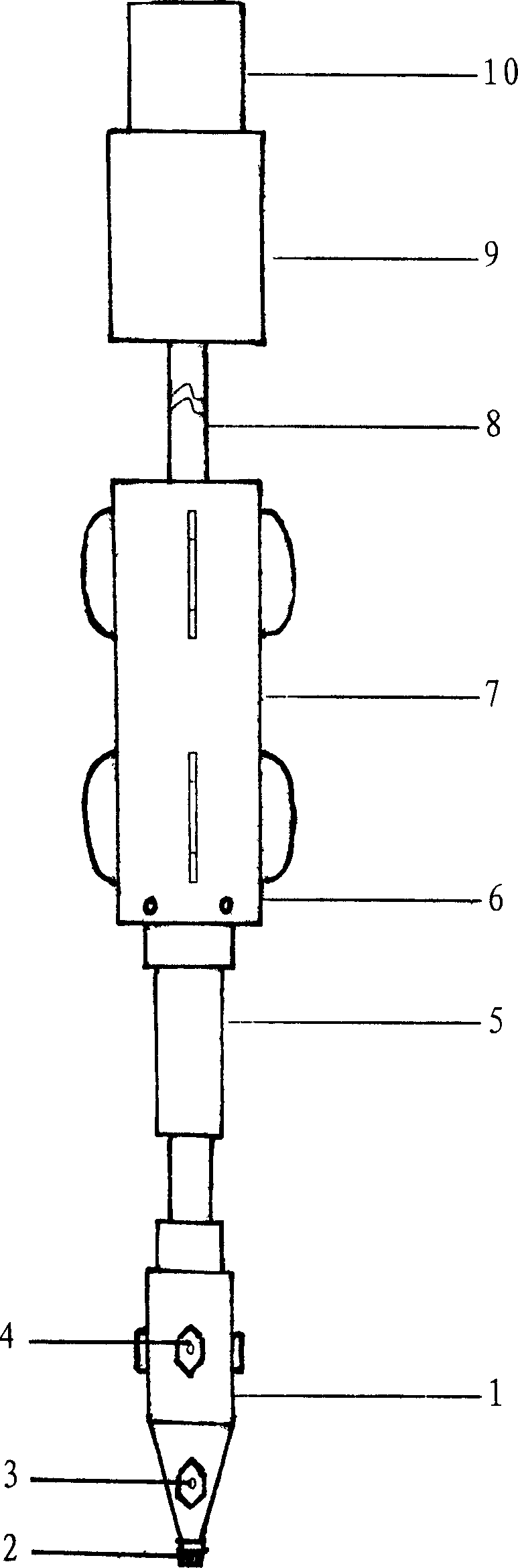
[0015] The invention consists of a jet head 1, a sand flushing nozzle 2, a couple nozzle 3, a cleaning nozzle 4, a damper 5, a guide 6, a pin 7, a flushing pipe 8 and a filter 9. It is characterized in that the screen of the filter 9 and The punching pipe 8 is threadedly connected, the punching pipe 8 is threadedly connected to the reducer joint of the damper through the center of the guide 6, the rotor of the damper 5 is connected to the damper body through a bearing, the damper rotor is threaded to the jet head 1, and the sand flushing nozzle 2 is installed on the axial top end of the jet head 1, the force couple nozzle 3 is installed laterally on the cone surface of the jet head at a certain phase angle, and the cleaning nozzle 4 is installed radially on the cylindrical...


PUM


Abstract

The present invention relates to a casing hydraulic pulse flushing device. It is composed of jet flow head, sand-cleaning nozzle, couple nozzle, cleaning nozzle, damper, guider, pin bolt, flushing pipe and filter. Said invention also provides their connection mode and working principle of said flushing device.

Description

1. Technical Field [0001] The invention relates to the technical field of oil extraction equipment, in particular to an in-pipe water pressure pulse washing device that uses high-pressure water jets to wash the sand control pipes in horizontal oil wells. 2. Background technology [0002] At present, the sand control tool commonly used in horizontal wells and highly deviated wells in oil fields is metal sand control pipes. In the production process, fine sand flowing out of the oil layer flows into the sand control pipes or blocks the pores of the sand control pipes, resulting in reduced production or shutdown. There is currently no suitable horizontal well A device for flushing in sand control pipes, therefore, there is an urgent need for a device suitable for flushing in sand control pipes in horizontal wells and highly deviated wells. Third, the content of the invention [0003] The purpose of the present invention is to provide an in-pipe water pressure pulse flushing device ...

Claims


Application Information

Patent Timeline
Patent Type & Authority Applications(China)
IPC IPC(8): E21B21/00E21B43/08
Inventor 陈辉张纪双宋岱锋吕金信贾斐
Owner 中国石化股份胜利油田分公司孤岛采油厂
Why Eureka
Try Eureka