Double-sensor laser visual measuring system calibrating method

A three-dimensional measurement and dual-sensor technology, applied in the field of measurement, can solve problems such as low calibration efficiency and complicated operation process, and achieve high calibration accuracy and measurement accuracy

A three-dimensional measurement and dual-sensor technology, applied in the field of measurement, can solve problems such as low calibration efficiency and complicated operation process, and achieve high calibration accuracy and measurement accuracy

CN1975324AInactive Publication Date: 2007-06-06HUANGSHI BANGKE TECH CO LTD

Image

  • Double-sensor laser visual measuring system calibrating method
  • Double-sensor laser visual measuring system calibrating method
  • Double-sensor laser visual measuring system calibrating method

Examples


Embodiment

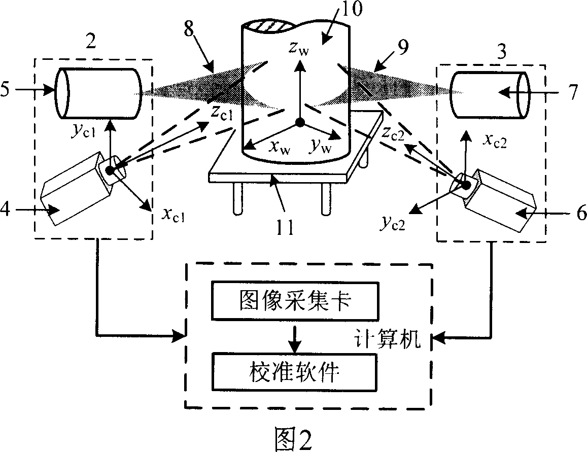
[0078] Two Mintron MS368P CCD cameras, Japanese Seiko lenses with focal lengths of 12mm and 16mm, and two line structured light projectors form a dual-sensor laser vision three-dimensional measurement system. The working distance of the sensor is within 600mm.

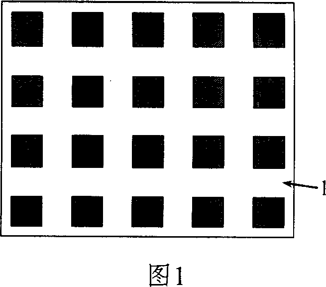
[0079] According to the steps described above, the model parameters of the dual-sensor laser vision three-dimensional measurement system were calibrated using the plane target shown in Figure 1. Within the measurement space range of each sensor, move 5 positions randomly, and use the image acquired by the CCD camera to extract feature points to calibrate the internal parameters of the camera. Turn on the power of the laser projector, ensure that the projected light strips pass through the characteristic area of ​​the target, move three positions randomly to obtain an image, and use the method described above to obtain control points on the light plane to calibrate the two light planes. The plane target is placed in the com...


PUM


Abstract

This invention disclosed a calibration technique for three-dimensional measure system. It can calibrate all the systematic model parameters in bi-sensor laser vision by using two-dimension plane drone, including the inner parameters of camera, camera coordinate system, etc. The advantages are as follows: no need for costly assistant equipment; high calibration precision; the process is brief and efficiency is high.

Description

Technical field [0001] The invention belongs to the field of measurement technology and relates to an improvement of a method for calibrating a model parameter of a dual-sensor laser vision three-dimensional measurement system. Background technique [0002] Laser vision measurement is an organic combination of laser technology and computer vision technology. It is one of the high and new technologies with development potential in the field of space three-dimensional precision measurement. It is used in the processing and manufacturing industries such as body size and mold profile measurement, as well as in the fields of face recognition. It has been well applied. According to the laser projection mode, laser vision 3D measurement can be divided into single-line structured light, multi-line structured light and grid structured light. [0003] A single structured optical vision sensor can constitute a single-sensor laser vision measurement system to complete the three-dimensional c...

Claims


Application Information

Patent Timeline
06 Jun 2007
Publication
CN1975324A
IPC
G01B11/00; G01B11/02; G01B11/24; H04N17/00
Inventors
周富强; 张广军