Imaging lens
一种摄像透镜、透镜的技术,应用在光学元件、光学、仪器等方向,能够解决很难小型轻量化与光学性能提高等问题,达到实现小型轻量化、制造性提高、提高制造性的效果
- Summary
- Abstract
- Description
- Claims
- Application Information
AI Technical Summary
Problems solved by technology
Method used
Image
Examples
no. 1 example
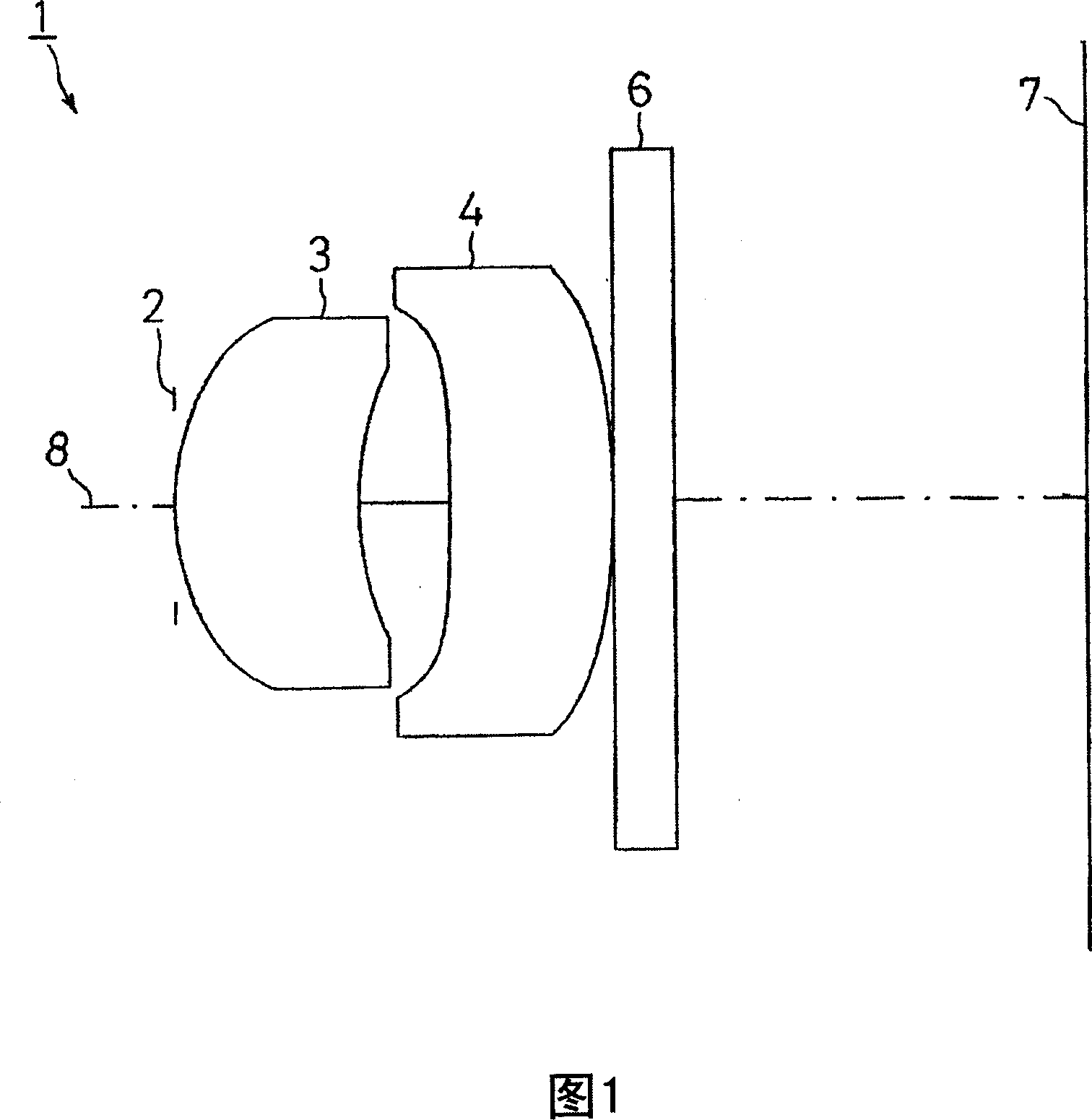
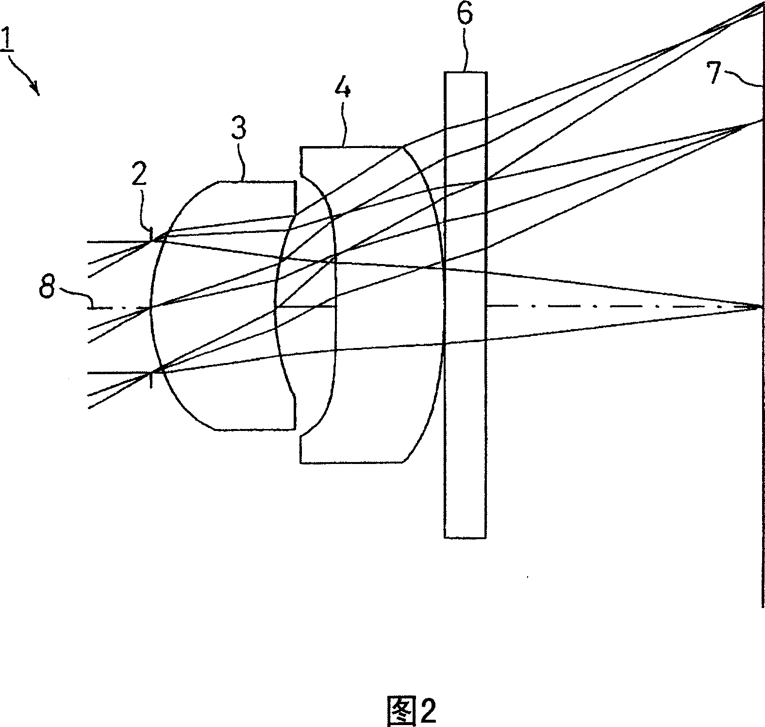
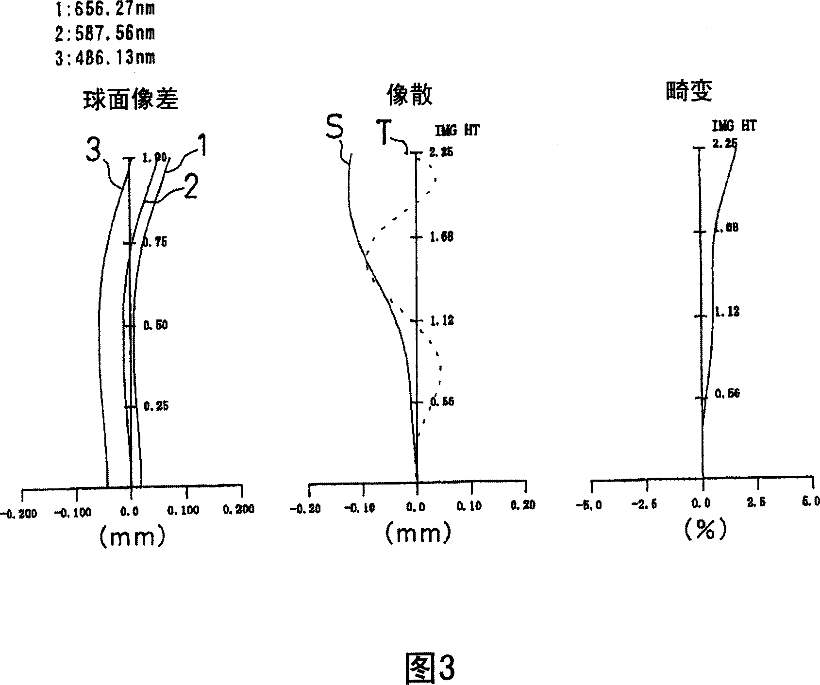
[0168] FIG. 2 shows a first embodiment of the present invention. In this embodiment, an iris diaphragm 2 is disposed on the object side of the first surface of the first lens 3 similarly to the imaging lens 1 having the structure shown in FIG. 1 , and A cover glass as a filter 6 is disposed between the second surface of the second lens 4 and the imaging surface 7 . In addition, the iris 2 is arranged at the same position in the direction of the optical axis 8 as the point on the optical axis 8 of the first surface of the first lens 3 .
[0169] The imaging lens 1 of this first embodiment is set by the following conditions.
[0170] lens data
[0171] L=4.34mm, fl=3.85mm, f 1 =5.18mm, f 2 =8.42mm, d 1 = 0.9 mm, d 2 =0.44mm, d 3 =0.8mm, Fno=4.0
[0172] Surface number r d nd υd
[0173] (part)
[0174] 1 (Iris diaphragm) 0.000 0.00
[0175] 2 (first surface of the first lens) 1.270 0.90 1.531 56.0
[0176] 3 (first lens second surface) 1.778 0.44
[0177] 4 (Second l...
no. 2 example
[0191] FIG. 4 shows a second embodiment of the present invention. In this embodiment, an iris diaphragm 2 is arranged on the object side of the first surface of the first lens 3 similarly to the imaging lens 1 having the structure shown in FIG. 1 , and A cover glass as a filter 6 is disposed between the second surface of the second lens 4 and the imaging surface 7 . In addition, the iris 2 is arranged at the same position in the direction of the optical axis 8 as the point on the optical axis 8 of the first surface of the first lens 3 .
[0192] The imaging lens 1 of this second embodiment is set by the following conditions.
[0193] lens data
[0194] L=2.19mm, fl=1.94mm, f 1 =2.7mm, f 2 =3.91mm, d 1 = 0.48mm, d 2 = 0.2mm, d 3 =0.4mm, Fno=4.0
[0195] Surface number r d nd υd
[0196] (part)
[0197] 1 (Iris diaphragm) 0.000 0.00
[0198] 2 (first surface of the first lens) 0.645 0.48 1.531 56.0
[0199] 3 (first lens second surface) 0.870 0.20
[0200] 4 (Second ...
no. 3 example
[0214] FIG. 6 shows a third embodiment of the present invention. In this embodiment, an iris diaphragm 2 is disposed on the object side of the first surface of the first lens 3 similarly to the imaging lens 1 having the structure shown in FIG. 1 , and A cover glass as a filter 6 is disposed between the second surface of the second lens 4 and the imaging surface 7 . In addition, the iris 2 is arranged at the same position in the direction of the optical axis 8 as the point on the optical axis 8 of the first surface of the first lens 3 .
[0215] The imaging lens 1 of this third embodiment is set by the following conditions.
[0216] lens data
[0217] L=2.09mm, fl=1.86mm, f 1 =2.37mm, f 2 =4.55mm, d 1 = 0.5mm, d 2 =0.18mm, d 3 =0.4mm, Fno=4.0
[0218] Surface number r d nd υd
[0219] (part)
[0220] 1 (Iris diaphragm) 0.000 0.00
[0221] 2 (first surface of the first lens) 0.625 0.50 1.525 56.0
[0222] 3 (first lens second surface) 0.909 0.18
[0223] 4 (Second le...
PUM
 Abstract
Description
Claims
Application Information
 - R&D
- Intellectual Property
- Life Sciences
- Materials
- Tech Scout
- Unparalleled Data Quality
- Higher Quality Content
- 60% Fewer Hallucinations
Browse by: Latest US Patents, China's latest patents, Technical Efficacy Thesaurus, Application Domain, Technology Topic, Popular Technical Reports.
© 2025 PatSnap. All rights reserved.Legal|Privacy policy|Modern Slavery Act Transparency Statement|Sitemap|About US| Contact US: help@patsnap.com


