Supercharge Your Innovation With Domain-Expert AI Agents!

Light influencing device

A technology of light and optical functions, applied in the directions of optics, optical elements, nonlinear optics, etc., to achieve the effect of rapid deflection

Active Publication Date: 2011-04-20
炬光(海宁)光电有限公司
View PDF1 Cites 0 Cited by
  • Summary
  • Abstract
  • Description
  • Claims
  • Application Information

AI Technical Summary

Problems solved by technology

[0004]A disadvantage of this type of device is that it is not possible to use broadband laser sources, such as semiconductor lasers, because the first lens element is in the plane of the first phase changing element array. Imaging depends on the wavelength of the light used

Method used


Image

  • Light influencing device
  • Light influencing device
  • Light influencing device

Examples


Embodiment Construction

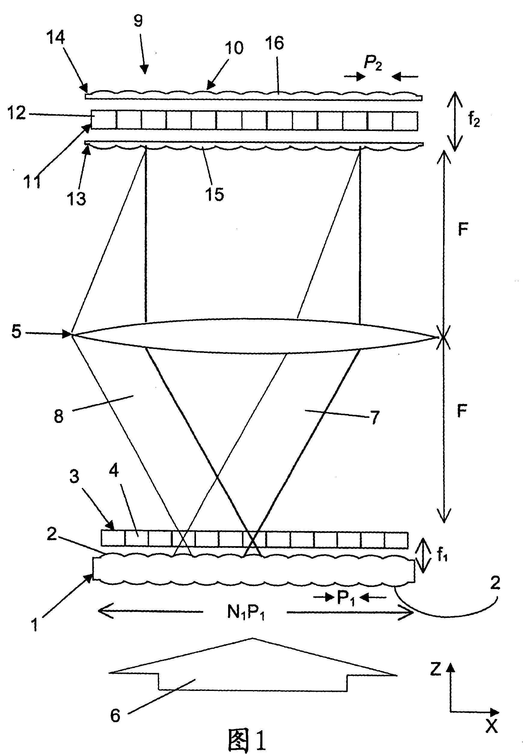
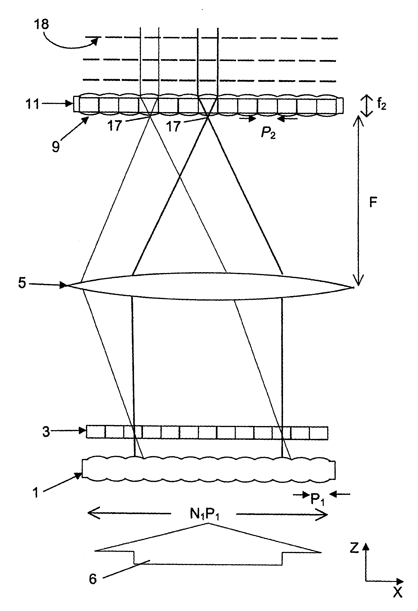
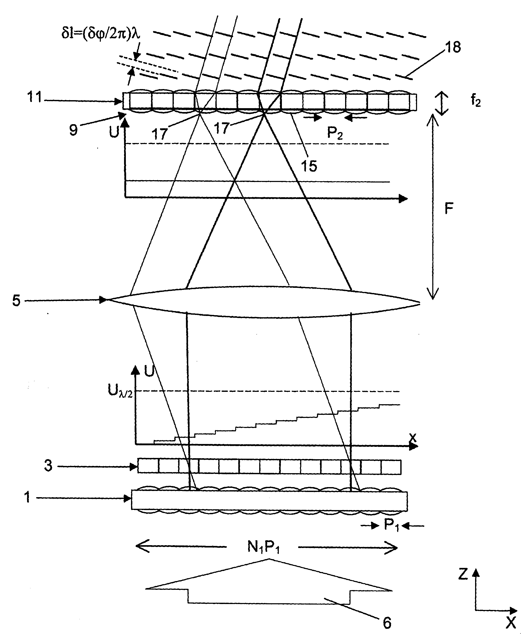
[0032] An embodiment of a device for influencing light shown in FIGS. 1 to 4 comprises a first array 1 of lens elements 2 . These lens elements 2 can be cylindrical lenses arranged adjacently in the X direction, which have a cylindrical axis pointing in the Y direction. These lenticular lenses can be configured as biconvex or plano-convex lenses. Furthermore, it is also possible to have two substrates on which a respective plano-convex lenticular lens is formed. A spherical lens may also be used instead of a cylindrical lens.

[0033] The embodiment of the device according to the invention shown in FIGS. 1 to 4 also comprises a first array 3 of phase changing elements 4 . The phase changing elements 4 are adjacently arranged in the X direction. The number of phase changing elements 4 corresponds to the number of lens elements 2 in the shown embodiment. The phase-modifying elements 4 are arranged in the region of the output-side focal plane of the lens elements 2 such that ...


PUM

PropertyMeasurementUnit
diameteraaaaaaaaaa
diameteraaaaaaaaaa

Abstract

The invention relates to a device for influencing light, include a first array of lens systems through which the light to be influenced can at least partially pass. A first phase-modifying array modulates the phases of the light which has passed through the individual lens systems of the first array. A second array of lens systems is provided through which the light phase-modified by the phase modifiers can at least partially pass. The second array of lens systems causes a plurality of local intensity maxima of the light to be created in the propagation direction of the light in the region ofthe second array of lens systems. A first lens system is disposed between the first array of lens systems and the second array of lens systems and a second lens system is disposed between the first lens system and the second array of lens systems. The first phase-modifying array is disposed between the first and second lens systems.

Description

technical field [0001] The invention relates to a device for influencing light and to the use of such a device. [0002] Background technique [0003] Definition: The mean direction of propagation of a ray is the direction of propagation of the ray to be affected, especially when the ray is not a plane wave or is at least partially divergent. If no other indication is given, a ray, part of a ray or ray does not refer to an ideal ray in geometrical optics, but to an actual ray of light, such as a light ray with a Gaussian profile, which does not have an infinitesimal ray cross-section, whereas is a ray section with an extension. [0004] US 6 341 136 B1 discloses a device of the above-mentioned type. In the device it describes, the first array of phase-altering elements is arranged immediately behind the first array of lens elements, in particular in its output-side focal plane. Furthermore, there is a second array of phase-altering elements, which is arranged at a short d...

Claims


Application Information

Patent Timeline
Patent Type & Authority Patents(China)
IPC IPC(8): G02F1/29G02B3/00
CPCG02F2203/04G02B27/0087G02F1/292G02B27/0961G02B27/10G02B3/00G02F1/00
Inventor 维塔利杰·利索塔奇恩库阿里克西·米科哈洛夫尤瑞·米科利阿维麦克希姆·达什特
Owner 炬光(海宁)光电有限公司
Features
  • R&D
  • Intellectual Property
  • Life Sciences
  • Materials
  • Tech Scout
  • Unparalleled Data Quality
  • Higher Quality Content
  • 60% Fewer Hallucinations
Learn More