Mould for continuous casting metal

A crystallizer and metal technology, applied in the field of crystallizers, can solve problems such as insufficient consideration of heat flow distribution, and achieve the effect of avoiding stress concentration

Inactive Publication Date: 2007-06-13
KME GERMANY GMBH & CO KG
View PDF4 Cites 13 Cited by
  • Summary
  • Abstract
  • Description
  • Claims
  • Application Information

AI Technical Summary

Problems solved by technology

All these literatures do not adequately consider the actual heat flow distribution

Method used


Image

  • Mould for continuous casting metal

Examples


Embodiment Construction

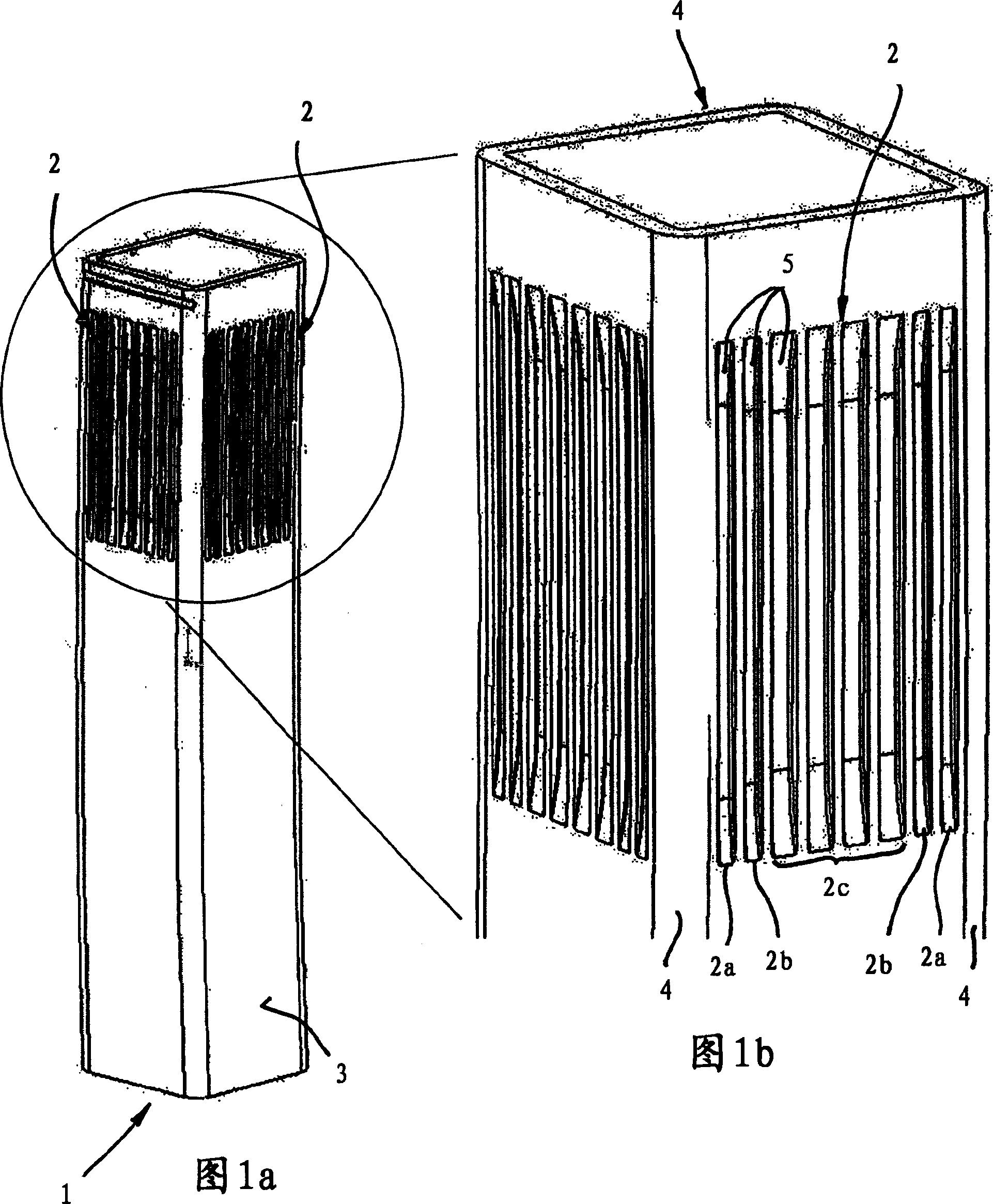
[0019] FIGS. 1 a and 1 b show a perspective view and an enlarged perspective view of a tubular crystallizer 1 , which is positioned in a tank in a manner not described in detail. Special features in this tubular crystallizer 1 are specially designed cooling channels 2 , which are formed on the outer surface 3 of the tubular crystallizer 1 . The cooling channels 2 do not extend over the entire length of the tubular crystallizer 1 , but are only present in the region of the upper injection side of the tubular crystallizer 1 . In this embodiment, the length of the cooling groove 2 is 200mm. The cooling trough 2 is present in the region of the set point of the fill level, the set point of the fill level being in the upper quarter of the cooling trough 2 described. The peculiarity in the cooling channels 2 of the tubular mold is that they are not all of the same width and depth, but are different in width and depth. In the present exemplary embodiment, the outer cooling grooves 2...


PUM

PropertyMeasurementUnit
widthaaaaaaaaaa

Abstract

The invention relates to a crystallizer (1) for continuous casting metal, wherein cooling vats (2, 2a, 2b, 2c) are arranged at least one part region of the crystallizer outer surface. The depth and / or width of cooling vats (2, 2a, 2b, 2c) in centre of the crystallizer (1) parietal side is maximal, and minish in the direction of corner regions (4) of inner parietal side. Thereby, heat dispersed uniformly and higher casting speed is possible with said heat dispersing.

Description

technical field [0001] The invention relates to a mold for continuous casting of metals having the features stated in the preamble of claim 1 . Background technique [0002] Tubular molds made of copper or copper alloys for casting profiles of steel or other metals with a high melting point are known in many ways from the prior art. Tubular molds generally have a uniform wall thickness in a horizontal cross-section, which increases in the direction of continuous casting due to the internal taper of the tubular mold. This internal taper is adapted to the solidification behavior of the strand and the casting parameters. Shortly after the start of solidification of the continuously cast material, ie directly below the casting liquid level, due to the three-dimensionally manifested heat dissipation in the cross section, a strongly differently manifested cooling behavior of the cast strand occurs. Since a particularly large amount of heat is dissipated at the corners of the tub...

Claims


Application Information

Patent Timeline
Patent Type & Authority Applications(China)
IPC IPC(8): B22D11/10
CPCB22D11/055B22D11/041B22D11/124C22C9/00
Inventor H-G·沃贝尔G·胡根许特D·科尔贝克R·博尔特F·麦瓦尔德D·赖内尔特H-D·皮沃瓦尔D·罗德
Owner KME GERMANY GMBH & CO KG
Why Eureka
Try Eureka