Electro-hydraulic brake system

A hydraulic braking and electronic technology, applied in the direction of brakes, brake components, control valves and air release valves, etc., can solve the problems of EHB system reliability and durability deterioration, master cylinder installation, low use versatility, etc.

Inactive Publication Date: 2007-06-13
HL MANDO CORP
View PDF0 Cites 32 Cited by
  • Summary
  • Abstract
  • Description
  • Claims
  • Application Information

AI Technical Summary

Problems solved by technology

Therefore, when the seal member provided around the outer circumference of the piston linearly reciprocates by passing through the step portion, there is a high possibility of damage to the seal member, which leads to deterioration of the reliability and durability of the EHB system.
[0009] Furthermore, the master cylinder of the EHB system disclosed in the prior art suffers from low space utility because it includes a different drilling structure than other general master cylinders and requires simulator installation space outside the master cylinder
In addition, it is impossible to install the master cylinder used in the general-purpose ABS or ESP system in the EHB system, and therefore, the master cylinder of the EHB system has low versatility of use

Method used


Image

  • Electro-hydraulic brake system
  • Electro-hydraulic brake system

Examples


Embodiment Construction

[0021] Reference will now be made in detail to the exemplary embodiments of the present invention, examples of which are illustrated in the drawings, wherein like reference numerals refer to like elements throughout. The embodiments are described below to explain the present invention by referring to the figures.

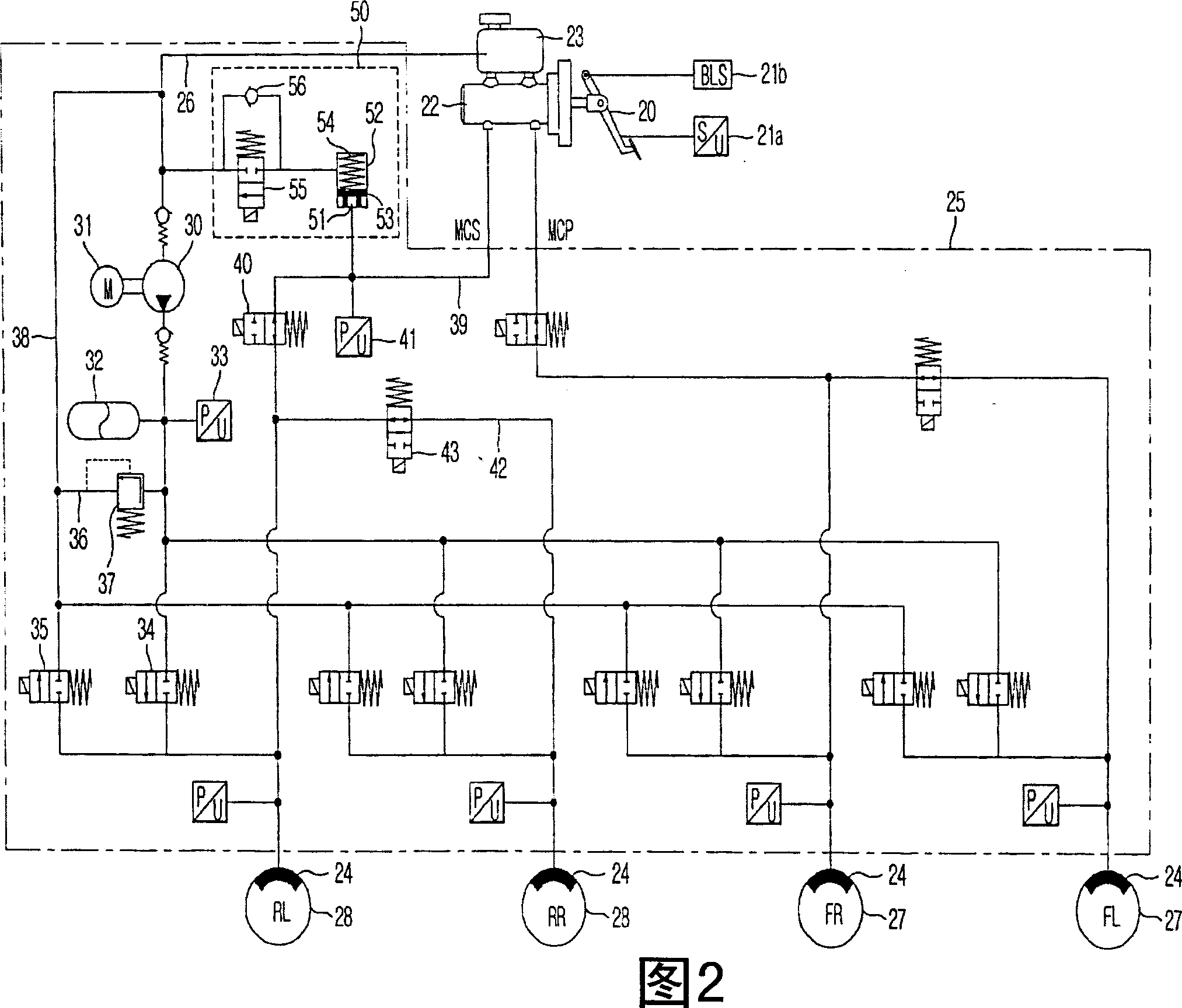
[0022] Fig. 2 is a schematic diagram of a hydraulic circuit of an EHB system according to a preferred embodiment of the present invention.

[0023] Referring to FIG. 2, the electronic hydraulic braking system (hereinafter referred to as "EHB" system) according to the present invention includes a brake pedal 20 for being operated by the driver of the vehicle when performing a braking operation, for receiving a master cylinder 22 that transmits the force, an oil reservoir 23 located on top of the master cylinder 22 and for storing oil therein, a wheel cylinder 24 that receives oil released from the oil reservoir 23 and is used for braking the respective brake wheels 2...


PUM


Abstract

An electro-hydraulic brake (EHB) system including a pump to pump and discharge oil in a reservoir, an accumulator to temporarily store the oil discharged from the pump, inlet valves to deliver the oil stored in the accumulator into the respective wheel cylinders, a return flow path connecting the wheel cylinders to the reservoir, outlet valves provided on the return flow path and adapted to discharge the oil from the wheel cylinders to the reservoir, cut-off valves to open and close flow paths between the wheel cylinders and an exit of a master cylinder, and a simulator. The simulator includes a first chamber communicating with the exit of the master cylinder, a second chamber connected to an entrance of the pump, and a simulator valve. The simulator having the above described configuration is able to prevent deterioration in the reliability and durability of the EHB system and to reduce the installation space of the master cylinder.

Description

[0001] Cross References to Related Inventions [0002] This application claims the benefit of Korean Patent Application No. 2005-0118572 filed in the Korean Intellectual Property Office on December 7, 2005, the disclosure of which is incorporated herein by reference. field of invention [0003] The present invention relates to an electro-hydraulic braking (EHB) system, and more particularly to an electro-hydraulic braking system capable of performing analog functions. Background technique [0004] Figure 1 shows a conventional electro-hydraulic braking system. [0005] In the shown conventional electro-hydraulic brake system (hereinafter referred to as "EHB" system), if the driver of the vehicle presses the brake pedal 1, the displacement sensor 2 detects the displacement of the brake pedal 1 . Based on the detection result from the sensor 2 , the shutoff valve 3 is closed to separate the flow paths of the master cylinder 5 having the pedal simulator 4 and the wheel cylinde...

Claims


Application Information

Patent Timeline
Patent Type & Authority Applications(China)
IPC IPC(8): B60T8/34
CPCB60T8/4081B60T8/32
Inventor 黄涌晰
Owner HL MANDO CORP
Why Eureka
Try Eureka