Electronic defrost timer for mechanical refrigerator

A timer and electronic technology, applied in defrosting, electronic switches, applications, etc., can solve the problems of material and personal damage, reduced rotation speed of meshing gears, manpower, resources and management costs, etc.

Inactive Publication Date: 2007-06-13
PACIFIC CONTROLS
View PDF1 Cites 3 Cited by
  • Summary
  • Abstract
  • Description
  • Claims
  • Application Information

AI Technical Summary

Problems solved by technology

[0006] However, according to the conventional mechanical defrosting timer for mechanical refrigerators as described above, many molded parts such as gears, gear shafts, etc. should be changed to change the operating time of the mechanical defrosting timer, and it is difficult to accurately control Compression / Defrost Operating Time
Therefore, it is difficult to immediately respond to users' requests for different operating times, and it takes a lot of time to test molded parts, thereby greatly requiring manpower, resources, and management costs
[0007] In addition, since refrigerants used in refrigerators are increasingly likely to become explosive refrigerants due to the world's becoming tighter atmospheric restrictions (e.g., ozone depletion), and existing electrical contacts are exposed to the air, So it may explode causing material and personal damage, and friction noise may occur in the gears due to the reduction of the rotational speed of the meshing gears

Method used


Image

  • Electronic defrost timer for mechanical refrigerator
  • Electronic defrost timer for mechanical refrigerator
  • Electronic defrost timer for mechanical refrigerator

Examples


Embodiment Construction

[0023] Hereinafter, preferred embodiments of the present invention will be described in detail with reference to the accompanying drawings. The matters defined in the specification, such as detailed structures and elements, are only specific details provided to help those of ordinary skill in the art fully understand the present invention, and thus the present invention is not limited thereto.

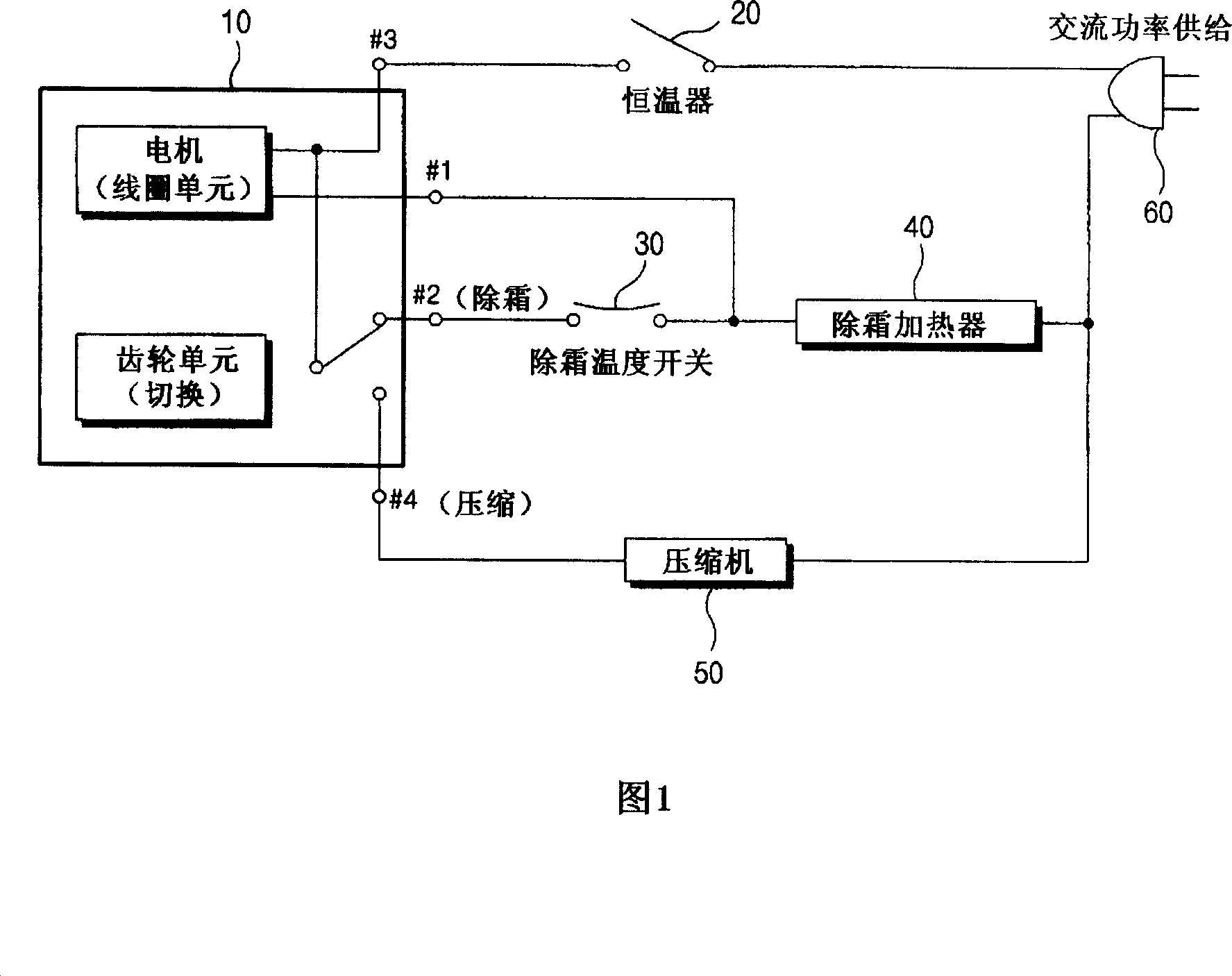
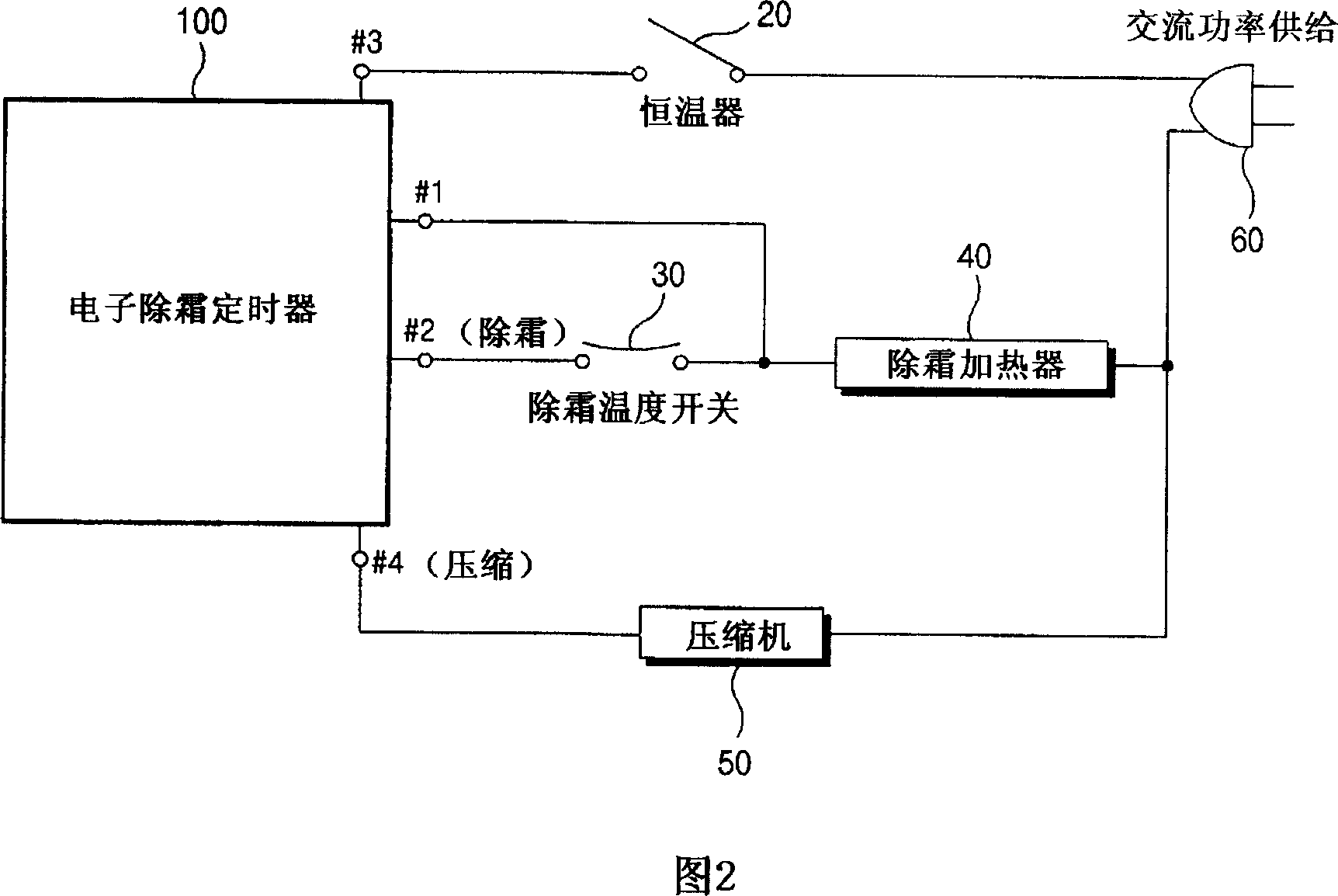
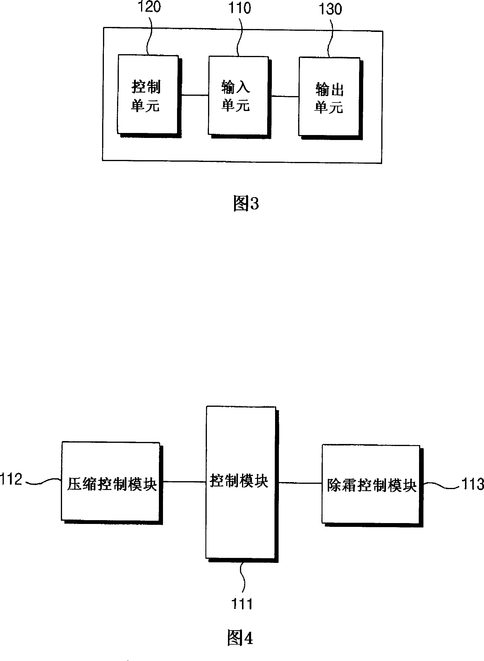
[0024] 2 is a schematic diagram illustrating the overall structure of an electronic defrost timer used in a mechanical refrigerator according to the present invention, and FIG. 3 is a block diagram illustrating the structure of the electronic defrost timer for a mechanical refrigerator according to an embodiment of the present invention.

[0025] Referring to Figures 2 and 3, the structure and operation of an electronic defrost timer for a mechanical refrigerator will now be described in detail.

[0026] As shown in FIG. 2, an electronic defrost timer 100 for a mechanical refrigerator ...


PUM


Abstract

An electronic defrost timer for a mechanical refrigerator is disclosed, which includes an input unit applying its power to the defrost timer and receiving an input of time for controlling the defrost timer, a control unit controlling a compression mode or a defrost mode by using the input time and a program, and an output unit directly controlling the compression mode or the defrost mode under the control of the control unit. According to the electronic defrost timer, since the input unit, the control unit, and the output unit are mounted on a PCB and the compression mode or the defrost mode is controlled by the program, the compression / defrost operation time of the refrigerator can be promptly controlled by a simple modification of the program, without any modification of moldings, and thus the manufacturing cost and time can be saved.

Description

[0001] Cross References to Related Applications [0002] This application is based on and claims priority from Korean Patent Application No. 10-2005-0118284 filed with the Korean Intellectual Property Office on December 6, 2005, the disclosure of which is hereby incorporated by reference in its entirety. technical field [0003] This invention relates to electronic defrost timers for mechanical refrigerators. More specifically, the present invention relates to an electronic defrost timer for a mechanical refrigerator, which is provided with an input unit, a control unit, and an output unit mounted on a printed circuit board (PCB), in a manner that is different from existing mechanical defrost timers. The same wiring and installation conditions of the refrigerator, and the compression mode and defrost mode are controlled by the program, so that the compression / defrost operation time of the refrigerator can be quickly controlled by simply changing the program without any molding...

Claims


Application Information

Patent Timeline
Patent Type & Authority Applications(China)
IPC IPC(8): F25D29/00F25D21/06H03K17/28
CPCF25D21/008F25D21/006F25D21/08F25D29/00F25D2400/361F25D2500/04
Inventor 李顺载
Owner PACIFIC CONTROLS
Why Eureka
Try Eureka