General motor and its stator lamination

A general-purpose motor and lamination technology, applied in the direction of electrical components, electromechanical devices, electric components, etc.

Inactive Publication Date: 2007-06-13
JOHNSON ELECTRIC SA
View PDF0 Cites 16 Cited by
  • Summary
  • Abstract
  • Description
  • Claims
  • Application Information

AI Technical Summary

Problems solved by technology

This situation is exacerbated if the pole neck is too narrow, saturating the stator poles

Method used


Image

  • General motor and its stator lamination
  • General motor and its stator lamination
  • General motor and its stator lamination

Examples


Embodiment Construction

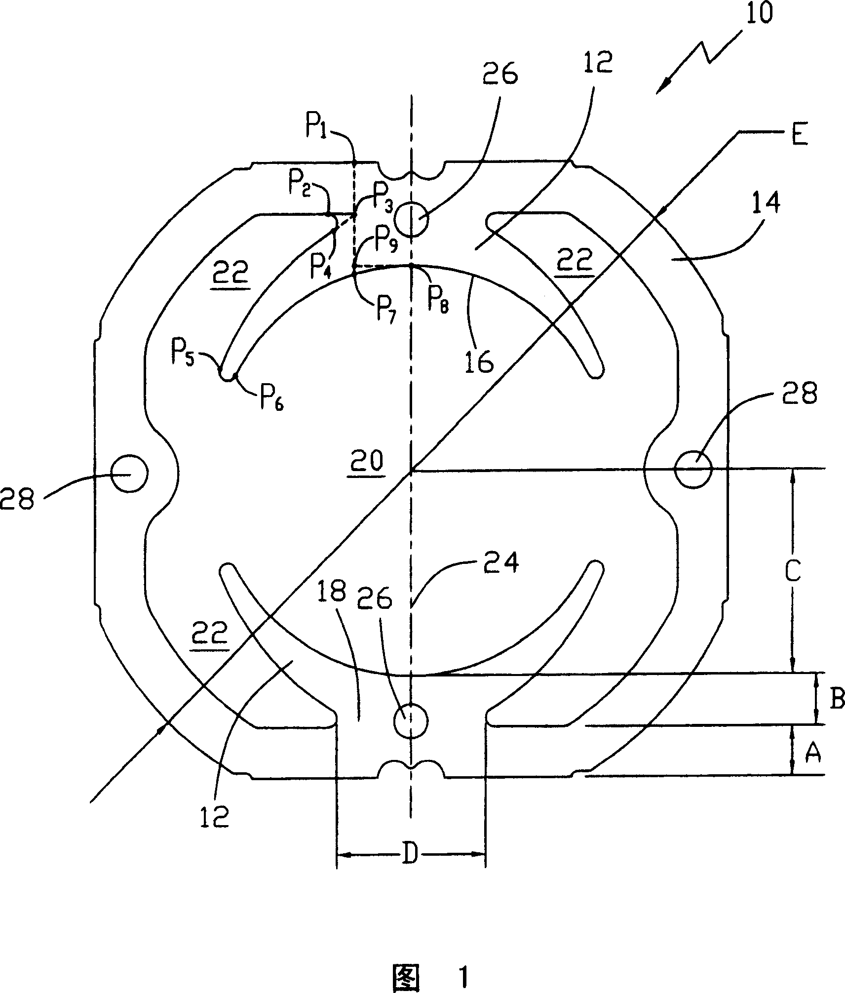
[0025] FIG. 1 shows a lamination 10' used in a lamination stator of a universal electric machine. The lamination 10 has two magnetic poles 12 connected to each other by a flux return path in the form of a ring 14 (also called a yoke). Each pole has an arcuate pole face 16 and a narrow or neck 18 connected to the ring. The pole faces extend towards each other and define between them a rotor space 20 which accommodates the rotor or armature. The field windings used are located around the neck in gaps or slots 22 (referred to as stator slots or field slots) formed between the ring and the poles. The poles face each other and extend along an imaginary line called pole axis 24 .

[0026] Holes 26 are optionally formed in the neck 18 of each pole 12 in the lamination 10 . The purpose of the hole is to reduce the weight of the laminations and to aid cooling of the pole. The placement of holes 26 is a matter of design choice and operational needs.

[0027] Two other holes 28 opti...


PUM


Abstract

Pile of stator of general motor possesses two magnetic poles, and magnetic flux return path as a ring connected to the two magnetic poles. Each magnetic pole possesses polar plane, which determines rotor space of accommodating rotor. Each magnetic pole possesses neck region for containing excitation winding of stator. Width of the ring, length of magnetic pole, and distance between polar planes, and width of neck region are selected based on equations of improved power output and output torque to be reached.

Description

technical field [0001] The present invention relates to general electric machines, and in particular to laminations for stator cores of general electric machines. Background technique [0002] Today's devices need to be smaller, lighter, and / or more powerful. This requirement places similar requirements on the motors that drive these devices. One common type of motor used to power household appliances such as power tools, kitchen appliances and vacuum cleaners is the small general purpose motor. These motors typically run between 8000 and 18000 rpm, typically with speeds up to 38000 rpm. Today's equipment requires general purpose motors to be lighter and / or smaller while having higher current ratings and better overload capabilities. [0003] For series general purpose motors, the direct-axis flux is proportional to field / armature current. The direct axis flux is the air gap flux generated by the field winding and distributed between the stator poles and the armature. T...

Claims


Application Information

Patent Timeline
Patent Type & Authority Applications(China)
IPC IPC(8): H02K1/12H02K1/14H02K1/02H02K3/00
CPCH02K1/146
Inventor 唐宪袁伟峰赵健
Owner JOHNSON ELECTRIC SA
Why Eureka
Try Eureka