Molten metal carrying apparatus using ladle

A technology for molten metal and conveying devices, applied in the field of molten metal conveying devices

Inactive Publication Date: 2007-06-20
西山 信六
View PDF1 Cites 6 Cited by
  • Summary
  • Abstract
  • Description
  • Claims
  • Application Information

AI Technical Summary

Problems solved by technology

[0003] However, if the ladle has to be transported to the pouring machine or to the casting site after receiving the molten metal,

Method used


Image

  • Molten metal carrying apparatus using ladle
  • Molten metal carrying apparatus using ladle
  • Molten metal carrying apparatus using ladle

Examples


Embodiment Construction

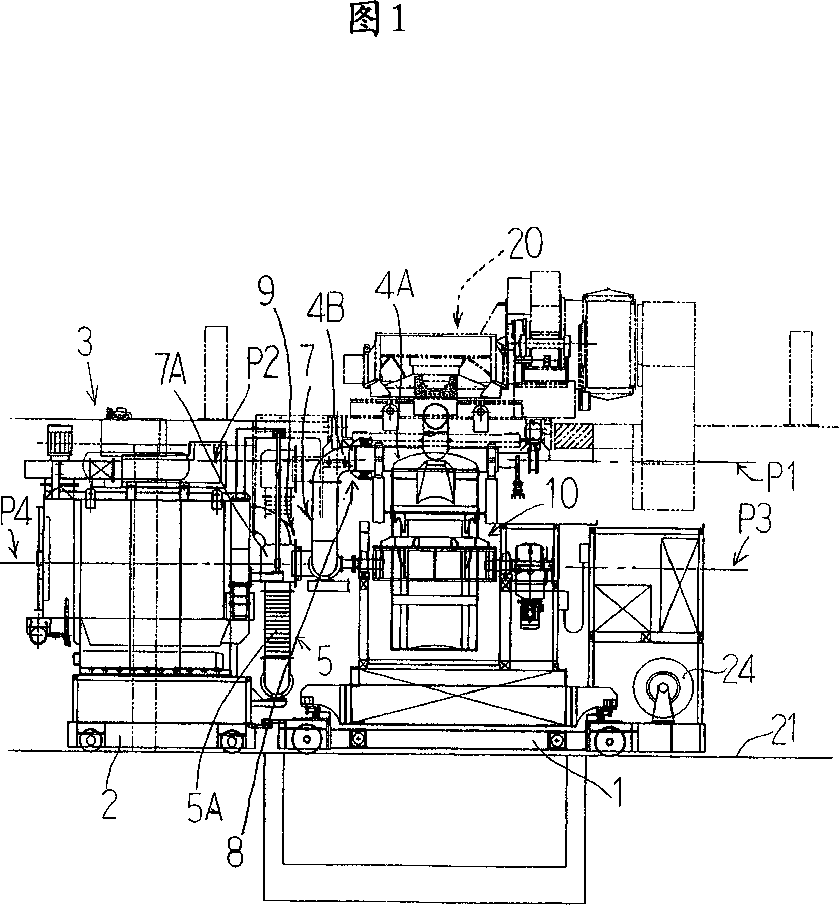
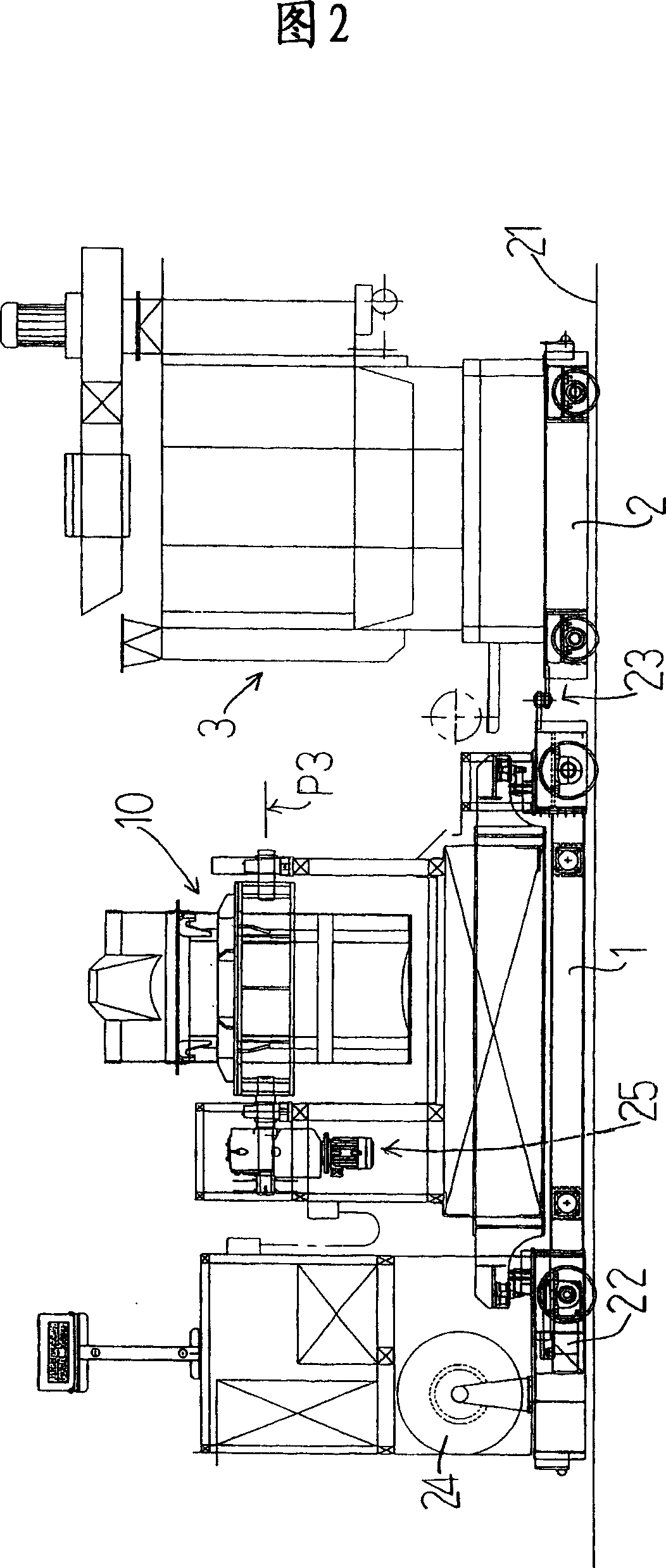
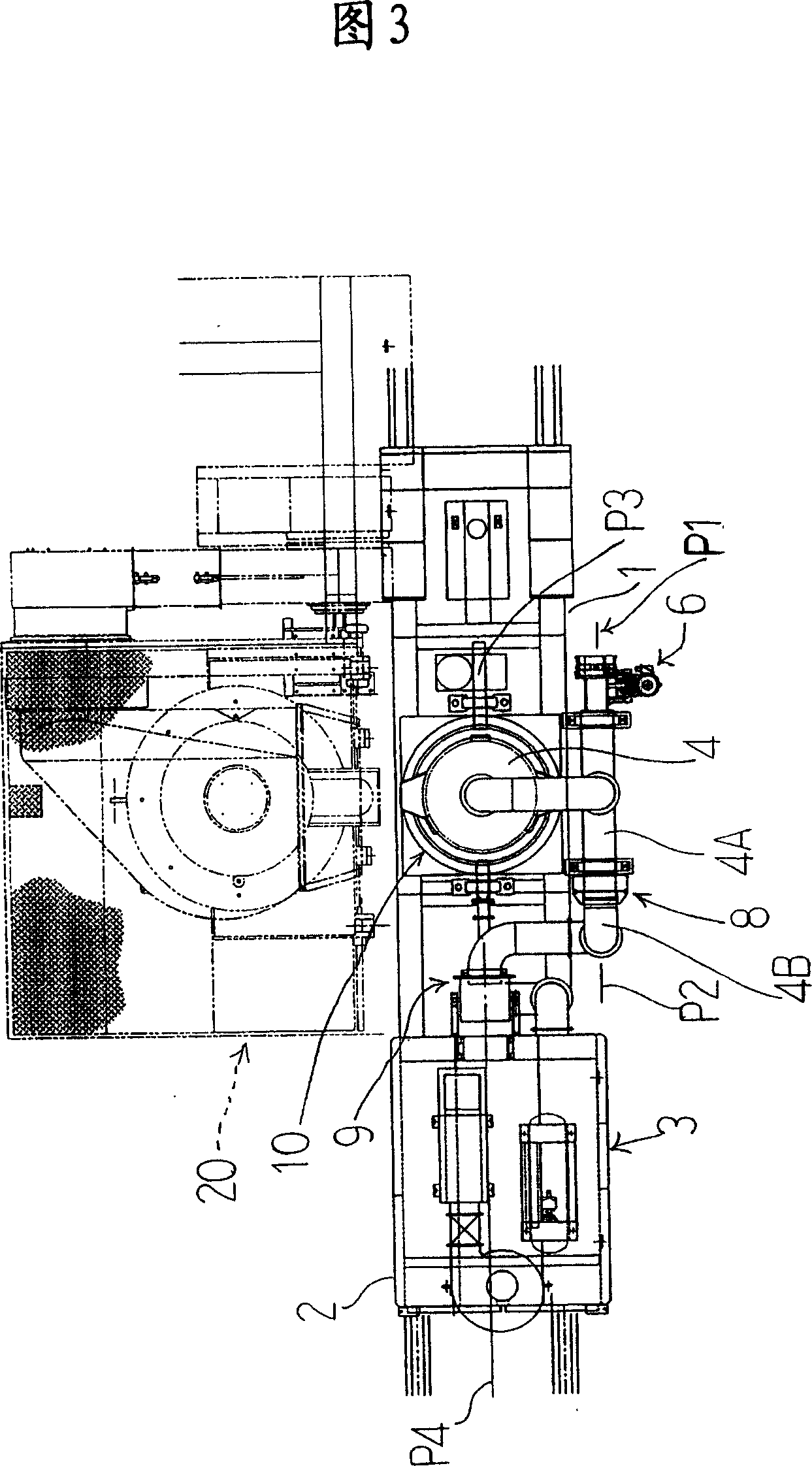
[0057] Hereinafter, a preferred embodiment of the molten metal conveying device using the ladle of the present invention will be described in detail based on FIGS. 1 to 7. In addition, the present invention is not limited to this embodiment without departing from the spirit of the present invention.

[0058] Fig. 1 is a front view of the molten metal conveying device stopped in front of an electric furnace 20, Fig. 2 is a back view thereof, Fig. 3 is a plan view thereof, and Fig. 4 is a side view thereof.

[0059] The molten metal conveying device is configured to freely move up, down and down on the ladle trolley 1 for receiving the molten metal from the electric furnace 20, and is configured to run automatically on a rail 21 laid in a factory. This self-propelled component is substantially the same component as a general electric vehicle, and a driving motor 22 is provided on the ladle trolley 1 and is configured to drive wheels. The power supply uses the cable tray 24 as shown ...


PUM


Abstract

The technology problem to be solved in the invention is to provide an apparatus for transporting molten metal using a ladle with which dust collection of soot, dust, etc., to the ascended/descended and tilled ladle can efficiently be performed without using a large scale apparatus as a whole, such as the conventional overhead crane type dust collecting system. A carrier 2 for a dust collector in a carrier 1 for ladle is arranged so as to be freely connected, and in the carrier 2 for dust collector, a bag filter type dust collector 3 is loaded and in the ladle 10, a cover type dust collecting hood 4 is arranged so as to be freely opened/closed. A primary moving connecting mechanism 8 in connect with a dust collector side duct 7 of the bag filter type dust collector 3 while permitting the opening/closing movement of the cover type dust collecting hood 4 is arranged and in the above dust collector side duct 7, a secondary moving connecting mechanism 9 for rotating around the tilting axial center P3 of the ladle 10 is arranged and a following means 5 is arranged in the dust collector side duct 7 so that the dust collector side duct 7 can follow with the ascending/descending of the ladle 10.

Description

Technical field [0001] The present invention relates to a molten metal conveying device using a ladle, which collects dust, smoke, soot, and dust generated by a molten metal conveying device (generally a ladle) of a foundry plant equipped with an electric furnace or the like. Background technique [0002] Various proposals are being made to improve the operating environment of foundry plants that generate a lot of soot and dust. Among them, the use of ring covers and other components to improve dust collection around electric furnaces is proposed to improve the collection of molten metal from the electric furnace to the ladle. For dust or dust collected from the ladle to the pouring machine, holding furnace or pouring from the ladle to the mold, it is combined with the aforementioned ring cover, and a separate dust collector and dust cover are installed near the ladle where the molten metal is discharged. Thereby eliminating the above dust collection. [0003] However, if the lad...

Claims


Application Information

Patent Timeline
IPC IPC(8): B22D41/12B08B15/04
CPCB22D41/12B66C23/201B22D41/04F24F7/003
Inventor 西山信六
Owner 西山 信六
Why Eureka
Try Eureka