Molten metal carrying apparatus using ladle

A technology for molten metal and conveying devices, applied in the field of molten metal conveying devices

Inactive Publication Date: 2010-06-09
西山 信六
View PDF4 Cites 0 Cited by
  • Summary
  • Abstract
  • Description
  • Claims
  • Application Information

AI Technical Summary

Problems solved by technology

[0003] However, if the ladle has to be transported to the pouring machine or to the casting site after receiving the molten metal, at this time, the soot and dust generated from the ladle spread in the factory, and countermeasures against it have been desired.

Method used


Image

  • Molten metal carrying apparatus using ladle
  • Molten metal carrying apparatus using ladle
  • Molten metal carrying apparatus using ladle

Examples


Embodiment Construction

[0057] Below, according to Figure 1 to Figure 7 A preferred embodiment of the molten metal conveying apparatus using a ladle of the present invention will be described in detail. In addition, this invention is not limited to this Example in the range which does not deviate from the gist.

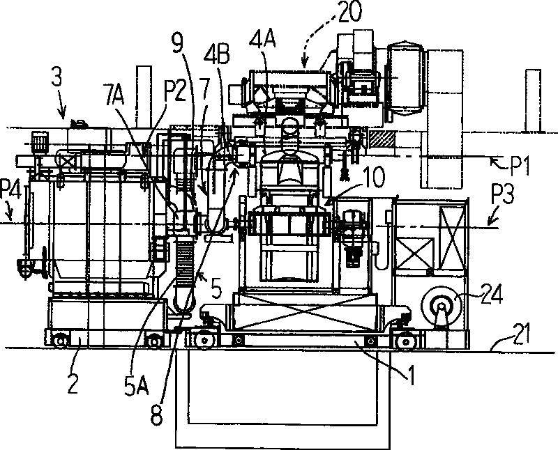
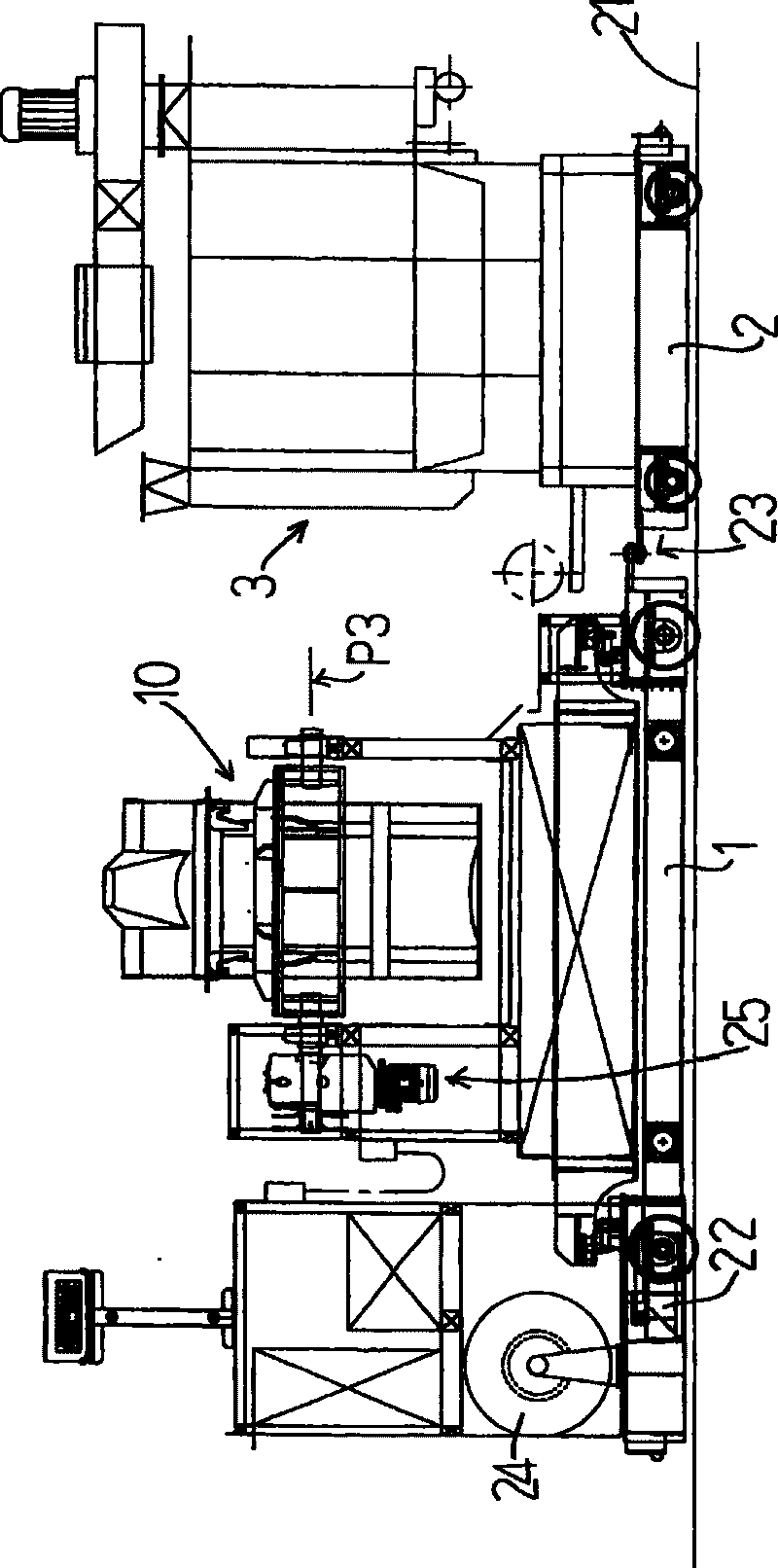
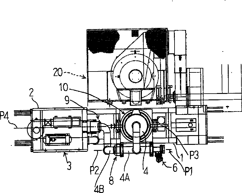
[0058] figure 1 It is a front view of the molten metal conveying device stopped in front of the electric furnace 20, figure 2 is its back view, image 3 is its floor plan, Figure 4 is its side view.

[0059] This molten metal transfer device is configured so that a ladle 10 for receiving molten metal from an electric furnace 20 is mounted on a ladle trolley 1 to be able to move up and down and tilt freely, and is configured to be able to run automatically on a rail 21 laid in a factory. This self-propelled unit is substantially the same as a general electric vehicle, and is provided with a drive motor 22 on the trolley 1 for ladles and is configured to drive wheels. power usage as ...


PUM


Abstract

The technology problem to be solved in the invention is to provide an apparatus for transporting molten metal using a ladle with which dust collection of soot, dust, etc., to the ascended / descended and tilled ladle can efficiently be performed without using a large scale apparatus as a whole, such as the conventional overhead crane type dust collecting system. A carrier 2 for a dust collector in acarrier 1 for ladle is arranged so as to be freely connected, and in the carrier 2 for dust collector, a bag filter type dust collector 3 is loaded and in the ladle 10, a cover type dust collecting hood 4 is arranged so as to be freely opened / closed. A primary moving connecting mechanism 8 in connect with a dust collector side duct 7 of the bag filter type dust collector 3 while permitting the opening / closing movement of the cover type dust collecting hood 4 is arranged and in the above dust collector side duct 7, a secondary moving connecting mechanism 9 for rotating around the tilting axialcenter P3 of the ladle 10 is arranged and a following means 5 is arranged in the dust collector side duct 7 so that the dust collector side duct 7 can follow with the ascending / descending of the ladle 10.

Description

technical field [0001] The present invention relates to a molten metal conveying device using a ladle that collects smoke, soot, and dust generated by a molten metal conveying device (generally a ladle) in a foundry equipped with an electric furnace or the like. Background technique [0002] Various proposals are being made to improve the working environment of foundry factories that generate a lot of soot and dust. Among them, ring covers and other components are used to improve dust collection around the electric furnace. For the dust collection from the ladle to the pouring machine, holding furnace or from the ladle to the casting mold, it is combined with the aforementioned annular cover, and a separate dust collector and dust collection cover are provided for the ladle adjacent to the place where the molten metal is discharged. Thereby eliminating the above dust collection. [0003] However, if the ladle has to be transported to the pouring machine or to the casting si...

Claims


Application Information

Patent Timeline
Patent Type & Authority Patents(China)
IPC IPC(8): B22D41/12B08B15/04
CPCB22D41/12B66C23/201B22D41/04F24F7/003
Inventor 西山信六
Owner 西山 信六
Why Eureka
Try Eureka