Air inlet unit of motor for vehicle

A technology for an air intake device and an engine, which is applied to the power plant, the arrangement combined with the gas intake of the power plant, and the cooling of the power plant, etc., can solve problems such as difficulties

Inactive Publication Date: 2007-06-20
SUZUKI MOTOR CORP
View PDF2 Cites 8 Cited by
  • Summary
  • Abstract
  • Description
  • Claims
  • Application Information

AI Technical Summary

Problems solved by technology

On the other hand, the design requires that the headlights be larger than before, and the air cleaner and the air intake passage on the upstream side of the air cleaner are placed in the engine room without affecting the shape of the headlight. is a difficult problem

Method used


Image

  • Air inlet unit of motor for vehicle
  • Air inlet unit of motor for vehicle
  • Air inlet unit of motor for vehicle

Examples


Embodiment Construction

[0022] Embodiments of the present invention will be described in detail below in conjunction with the accompanying drawings.

[0023] 1 to 5 show embodiments of the present invention.

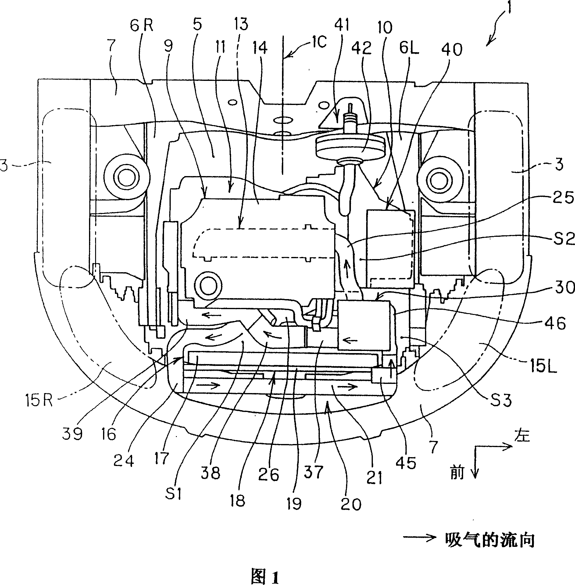
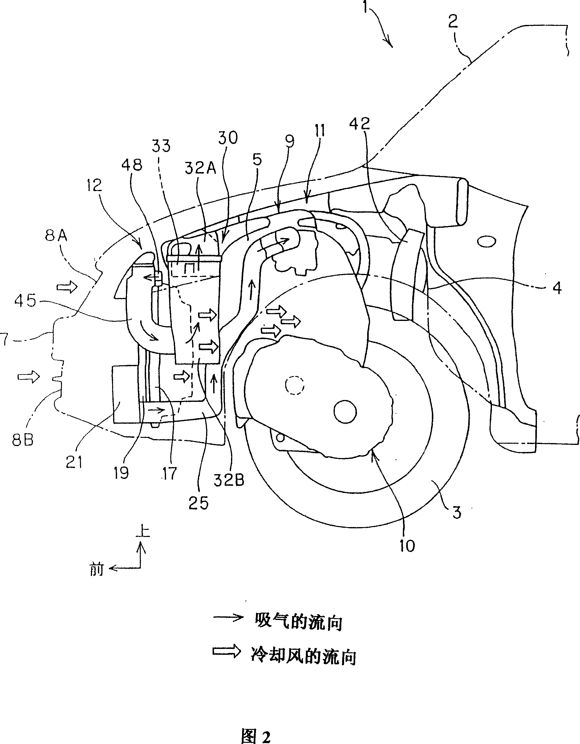
[0024] In Fig. 1 and Fig. 2, part number 1 is a vehicle, part number 2 is a vehicle body, and part number 3 is a front wheel. An engine compartment 5 is formed at the front of the vehicle 1 by partitions 4 extending in the lateral direction of the vehicle. A pair of left side members 6L and right side members 6R extending in the front-rear direction of the vehicle are provided at both sides of the engine room 5 in the vehicle transverse direction at a constant interval. In addition, at the front part of the engine room 5 in the front-rear direction of the vehicle, there is provided an arc-shaped front bumper 7 extending in the vehicle lateral direction and the central part protrudes toward the front of the vehicle. The upper side opening portion 8A and the lower side opening portion 8B throug...


PUM


Abstract

The invention relates to an air intake apparatus for a vehicle motor which having a structure of loading an engine and a transmission in an engine chamber in the front of the vehicle along a horizontal direction thereof. A fan baffle has a cylinder portion surrounding the out circumference of a radiator fan. The axis centre of the cylinder portion relatively passes a horzontal line of the center of the radiator core, while side deflecting a core upwards and downwards along a vertical direction, simultaneously, a concave for housing the fan baffle is provided on the bottom of an air filter housing configured as an air filter, which overlaps with the upper of the cylinder portion along a vertical direction and provided inside corresponding to a side member on a horizontal direction of the vehicle. Thereby, air intake system members are provided efficiently, while degree of freedom of a headlamp modelling is increased and originality is improved.

Description

technical field [0001] The present invention relates to an air intake device for a vehicle engine, in particular to a vehicle in which the engine and the transmission are mounted side by side in the vehicle front engine room in the vehicle transverse direction, while efficiently arranging the air intake system components and using the The air intake device of the vehicle engine improves the freedom of styling of the headlight and optimizes the appearance design performance. Background technique [0002] In a vehicle, an engine compartment is formed at the front of the vehicle, and an engine and a transmission are mounted side by side in the engine compartment in the vehicle transverse direction. Generally, a pair of headlights are provided at front corners of an engine compartment of a vehicle, and a radiator is provided between the pair of headlights. In addition, a radiator fan is mounted on the vehicle rear side of the radiator by means of a fan shroud. [0003] Convent...

Claims


Application Information

Patent Timeline
Patent Type & Authority Applications(China)
IPC IPC(8): B60K13/02
CPCB60K13/02B60K11/04F02M35/06
Inventor 山口博史
Owner SUZUKI MOTOR CORP
Why Eureka
Try Eureka