Aircraft trailing edge devices, including devices having forwardly positioned hinge lines, and associated methods

A hinged line, trailing edge technology, used in aircraft parts, aircraft control, transportation and packaging, to solve problems such as reducing the size and complexity of external fairings

Active Publication Date: 2007-06-20
THE BOEING CO
View PDF0 Cites 19 Cited by
  • Summary
  • Abstract
  • Description
  • Claims
  • Application Information

AI Technical Summary

Problems solved by technology

However, a potential disadvantage of this arrangement is that a complex mechanism is generally required to deploy the flaperon 60b to the rearward configuration, especially when the mechanism is configured to fit within the narrow wing section to reduce the outer fairing. size
On the other hand, simple mechanisms such as simple hinges tend to extend away from the profile of the wing section, requiring relatively large, heavy hinge supports and associated fairings that create drag

Method used


Image

  • Aircraft trailing edge devices, including devices having forwardly positioned hinge lines, and associated methods
  • Aircraft trailing edge devices, including devices having forwardly positioned hinge lines, and associated methods
  • Aircraft trailing edge devices, including devices having forwardly positioned hinge lines, and associated methods

Examples


Embodiment Construction

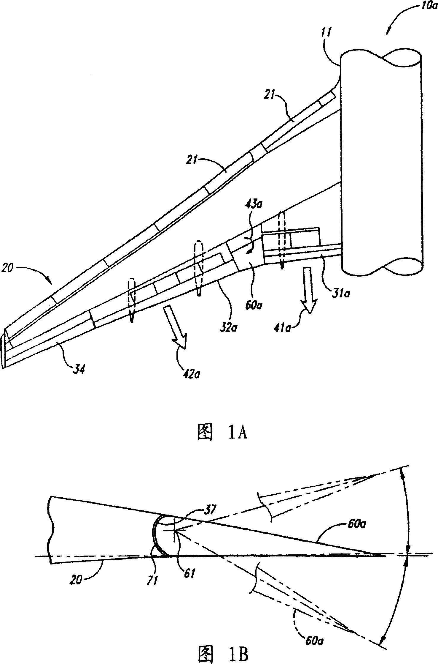
[0019] This disclosure describes aircraft trailing edge devices, including devices having non-parallel paths of motion, and related methods. Some specific details of the invention are set forth in the following description and Figures 2-6C to give a thorough understanding of certain embodiments of the invention. However, those skilled in the relevant art should understand that the present invention may have other embodiments, and the implementation of other embodiments of the present invention may not have some specific features described below.

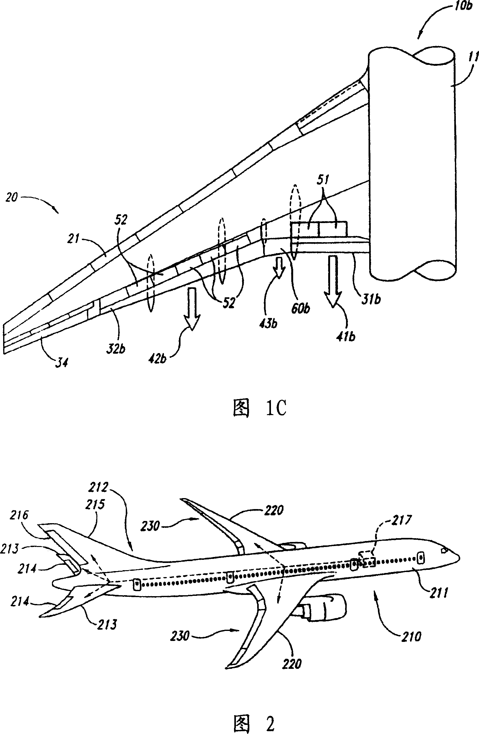
[0020] Figure 2 is a partial schematic illustration of an isometric view of an aircraft 210 having a fuselage 211 and a wing 220 fitted with a trailing edge device 230 arranged in accordance with an embodiment of the present invention. The aircraft 210 also includes an empennage 212 with a horizontal stabilizer 213 and a vertical stabilizer 215 . The horizontal stabilizer 213 has an elevator 214 and the vertical stabilizer 215 may h...


PUM


Abstract

Aircraft trailing edge devices, including devices having forwardly positioned hinge lines, and associated methods are disclosed. An aircraft system in accordance with one embodiment of the invention includes a wing and a trailing edge device coupled to the wing. The trailing edge device can be movable relative to the wing between a stowed position and a deployed position, with the trailing edge device having a leading edge, a trailing edge, an upper surface, and a lower surface. The upper surface can have an intersection point with the wing when the trailing edge device is in the stowed position. The motion of the trailing edge device relative to the wing can include rotational motion about a hinge line positioned forward of the intersection point, and a gap can be positioned between the trailing edge of the wing and the leading edge of the trailing edge device when the trailing edge device is in the deployed position.

Description

technical field [0001] The present invention is generally directed to aircraft trailing edge devices, including devices having forward hinge lines, and related methods. Background technique [0002] Modern high-speed aircraft basically have thin wings that provide a low-drag curve during high-speed flight or cruise. The wings of these aircraft typically include various movable surfaces to provide aircraft control and / or to configure the aircraft for low-speed operation (eg, takeoff and landing). For example, in addition to carrying fuel, the wings of high speed transport aircraft typically include aileron surfaces, spoiler surfaces, leading edge devices, and trailing edge flap surfaces. These moveable surfaces are typically located at or adjacent to the leading and trailing edges of the wings, and are each movable between a retracted position and a number of deployed positions, depending on the particular flight conditions of the aircraft. [0003] Figure 1A is a partial s...

Claims


Application Information

Patent Timeline
Patent Type & Authority Applications(China)
IPC IPC(8): B64C9/20
CPCB64C9/16B64C9/18Y02T50/32Y02T50/30
Inventor 道格拉斯·S·莱西简·A·科戴尔约翰·V·多维迈克尔·A·巴尔泽塞亚·萨库莱尼尔·V·休恩
Owner THE BOEING CO
Why Eureka
Try Eureka