Hydraulic turbine

A water turbine and hydraulic technology, applied in impact engines, hydroelectric power generation, mechanical equipment, etc., can solve problems such as insufficient power supply, impact on people's production and life, and low utilization rate of water energy

Inactive Publication Date: 2007-06-20
何周坤
View PDF0 Cites 1 Cited by
  • Summary
  • Abstract
  • Description
  • Claims
  • Application Information

AI Technical Summary

Problems solved by technology

[0002] At present, several hydroelectric power stations have been built in our country, but the power supply is still insufficient, especially in the western rural areas, which often have power outages, whic

Method used


Image

  • Hydraulic turbine

Examples


Embodiment Construction

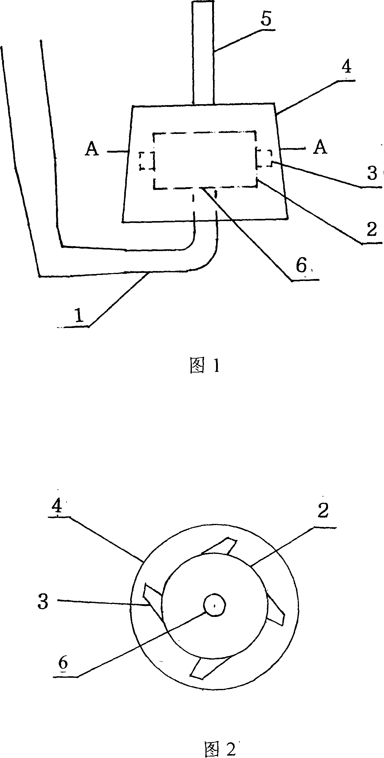
[0007] When the above-mentioned hydraulic water turbine enters the working state, the water flows in from the water inlet pipe (1), flows into the liquid cylinder (2) through the water inlet (6), and is sprayed out from the water spray port (3) to impact the runner (4). Wheel (4) just rotates together with transmission shaft (5), and the current after doing work falls along runner (4) inner wall.

[0008] Features of this machine:

[0009] When the water flow enters the water inlet pipe (1) due to the decreasing cross-section, a very high pressure has been generated when it reaches the water inlet (6), and then enters the hydraulic cylinder (2) to produce the same effect as the principle of the hydraulic machine, and the water flow is greatly increased. pressure, the thrust of water ejected from the water spout (3) increases, and the speed also increases thereupon, and the runner has just obtained extremely high kinetic energy.


PUM


Abstract

A hydraulic water turbine consists of a runner casing and a hydraulic cylinder. The runner casing is a round-table shape without a bottom and in the centre of the upper base is fixed a drive shaft. The hydraulic cylinder is covered in the runner casing. Around the cylinder there is a set of water spray nozzles and at the bottom of the cylinder there is a water inlet in communication with a water intake pipe.

Description

Technical field: [0001] The invention provides a water turbine for hydropower generation. technical background: [0002] At present, my country has built several hydroelectric power stations, but the power supply is still insufficient, especially in the western rural areas where there are frequent power outages, which have a great impact on people's production and life. According to the survey, there are many models with too much runoff hydropower to wash away the water, and the low utilization rate of water energy is one of the reasons. Invention content: [0003] The purpose of the present invention is to provide a hydraulic water turbine that can overcome the disadvantages of the known technology and improve the utilization rate of water energy. The turbine consists of a runner housing and a hydraulic cylinder. The runner shell is a circular frustum without a bottom. A transmission shaft is fixed in the center of the upper bottom. The liquid cylinder with the upper an...

Claims


Application Information

Patent Timeline
IPC IPC(8): F03B1/00F03B1/04
CPCY02E10/223Y02E10/20
Inventor 何周坤
Owner 何周坤
Why Eureka
Try Eureka