
Device and method for transmitting data in asynchronous clock domain

An asynchronous clock and domain transmission technology, applied in the field of data transmission, can solve the problems of impossible adjustment of data transmission delay in FIFO, FIFO can not meet transmission delay error, FIFO can not detect and other problems, to achieve simple effect

Inactive Publication Date: 2007-06-20
HUAWEI TECH CO LTD
View PDF0 Cites 19 Cited by
  • Summary
  • Abstract
  • Description
  • Claims
  • Application Information

AI Technical Summary

Problems solved by technology

However, when any of the read and write ports of the FIFO is abnormal and the read and write addresses jump, the FIFO cannot detect it, and it is impossible to adjust the transmission delay of the data in the FIFO, so the FIFO cannot meet the requirements for the transmission delay. Error Sensitive Applications

Method used


Image

  • Device and method for transmitting data in asynchronous clock domain
  • Device and method for transmitting data in asynchronous clock domain

Examples


Embodiment Construction

[0022] In order to make the purpose, technical solution and advantages of the present invention clearer, the following examples are given to further describe the present invention in detail.

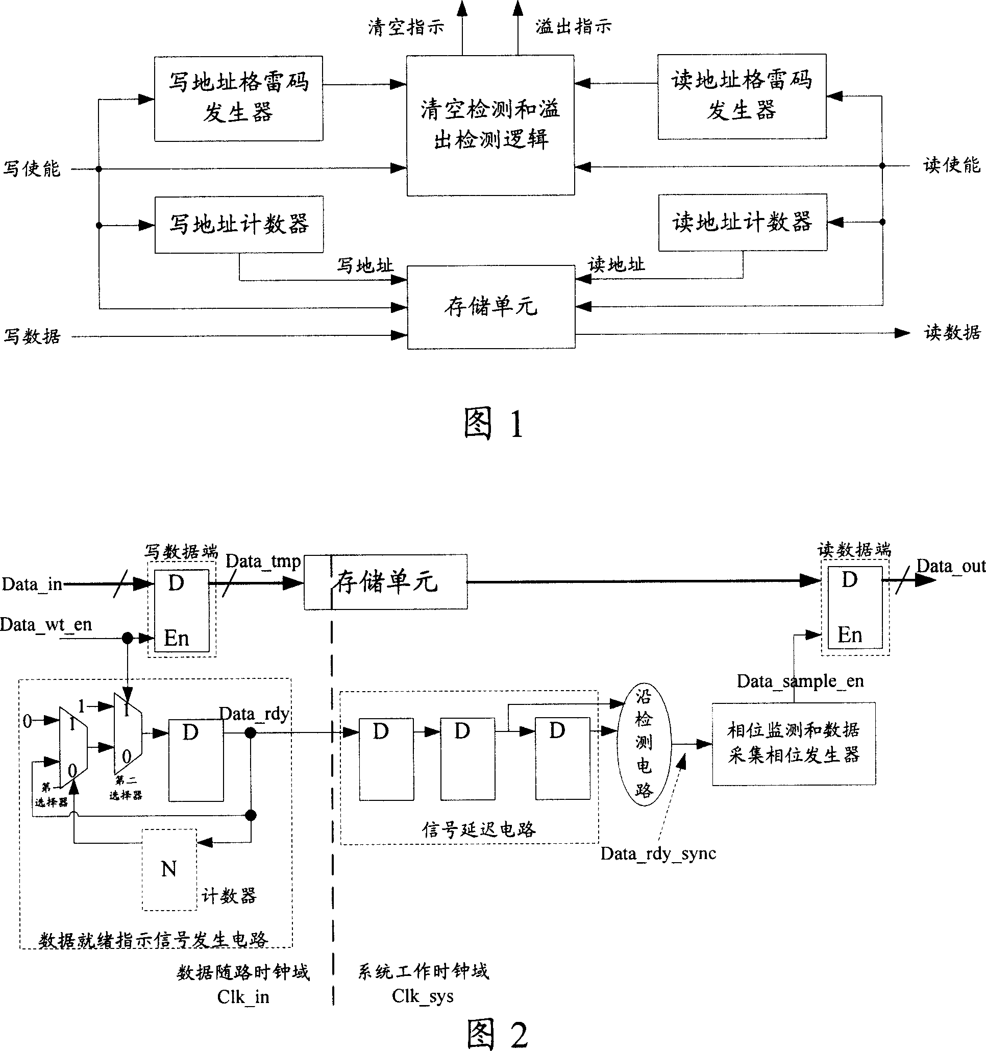
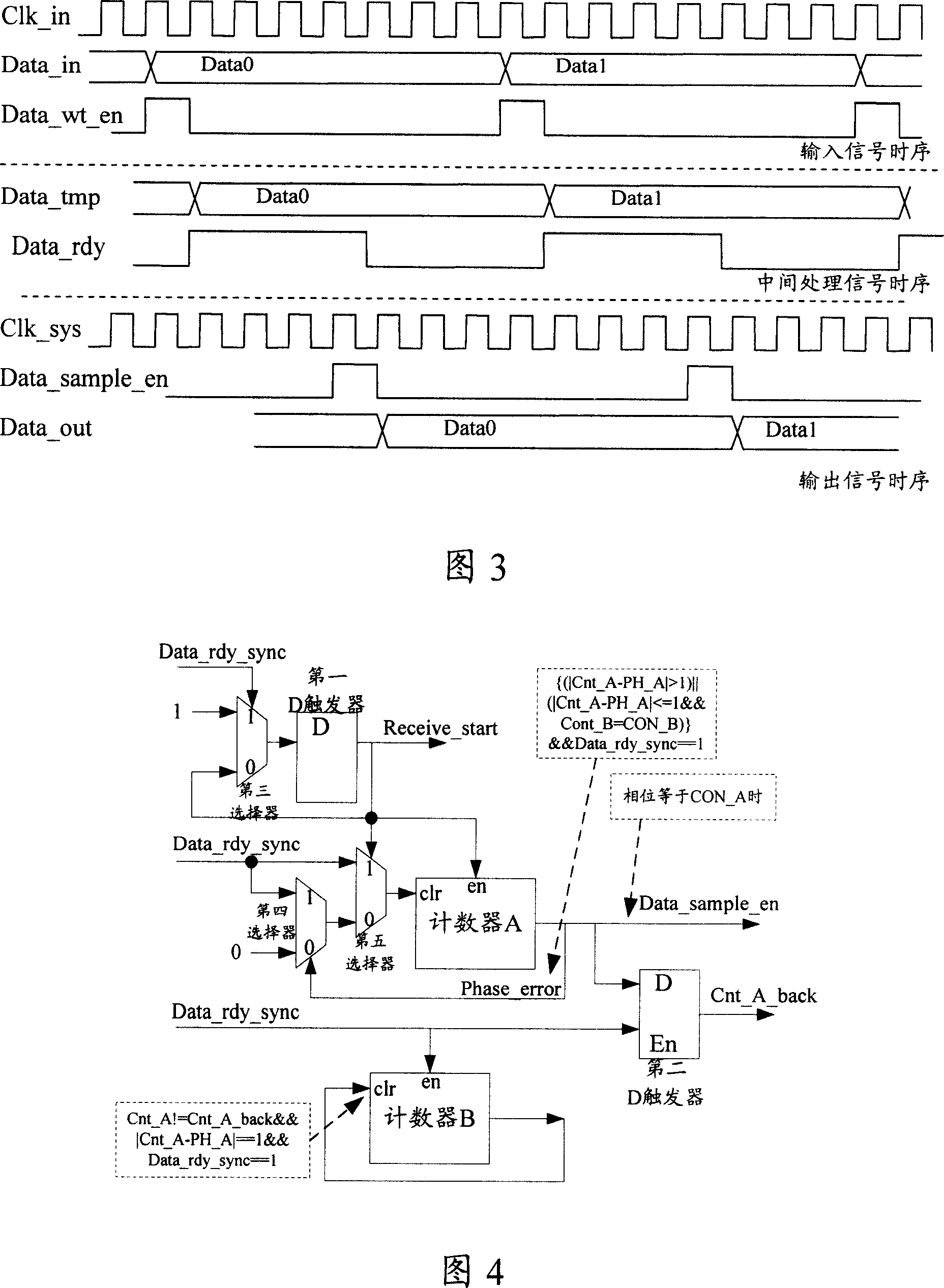
[0023] With reference to Fig. 2, the device that the present invention adopts comprises writing data end, storage unit, data ready indication signal generation circuit, signal delay circuit, edge detection circuit, phase monitoring and data acquisition phase generator, and read data end. Among them, the sender's write data terminal and data ready indication signal generation circuit work in the data follower clock domain Clk_in, and the receiver's signal delay circuit, edge detection circuit, phase monitoring and data acquisition phase generator, and read data terminal all work Work in the system clock domain Clk_sys. The structure and function of each part are introduced respectively below.

[0024] The write data terminal includes a D flip-flop, and when the write enable signal Data_w...


PUM


Abstract

A method for transmitting data in asynchronous clock domain includes storing data into storage unit and generating a data ready indication signal being sent to receiving party by sending party when energized writing signal is valid, generating data indication signal by receiving party when edge of said indication signal is detected, regulating phase of the first counter according to said indication signal and fetching data from storage unit when phase of the first counter is on preset phase.

Description

technical field [0001] The invention relates to the technical field of data transmission, in particular to a device and method for transmitting data in an asynchronous clock domain. Background technique [0002] In most systems, data is transmitted between different boards in a serial manner, while asynchronous clocks are used between different boards. However, even if the asynchronous clocks of different boards have the same source, because they are obtained through different phase-locked loops (PLL) or different channels, the respective clock signal jitters (Jitter) are different, and in any There will be a frequency difference in a short period of time, but the long-term statistical results show that they are synchronized to the clock source, so two clocks on different boards will have phase drift within a certain period of time, and the maximum value of the phase drift depends on The quality of components such as clock sources and PLLs. [0003] Most systems today use ...

Claims


Application Information

Patent Timeline
Patent Type & Authority Applications(China)
IPC IPC(8): G06F13/38
Inventor 吴奇祥
Owner HUAWEI TECH CO LTD
Learn More