
Transonic hull and hydrofield

A transonic and hull technology, applied in the direction of hull, hull design, hydrodynamic characteristics/hydrostatic characteristics, etc., can solve problems such as increased resistance and volume of the hull that are not priority

Inactive Publication Date: 2007-06-20
阿尔伯特·阿尔瓦雷斯-卡尔德伦
View PDF2 Cites 6 Cited by
  • Summary
  • Abstract
  • Description
  • Claims
  • Application Information

AI Technical Summary

Problems solved by technology

This adds drag and bulk to the design of the hull and the drag issue is not a priority for the state of the art

Method used


Image

  • Transonic hull and hydrofield
  • Transonic hull and hydrofield
  • Transonic hull and hydrofield

Examples


Embodiment Construction

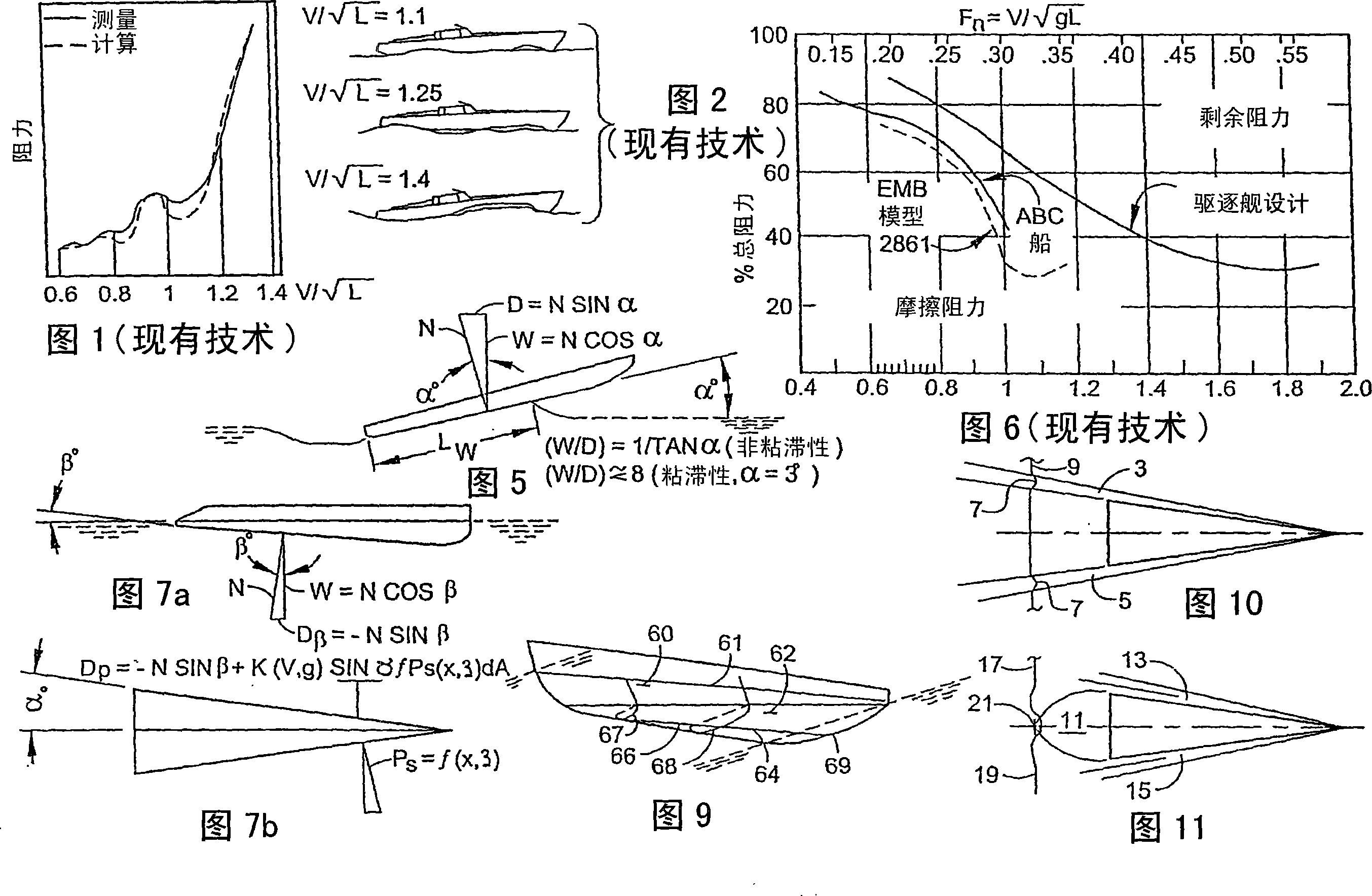
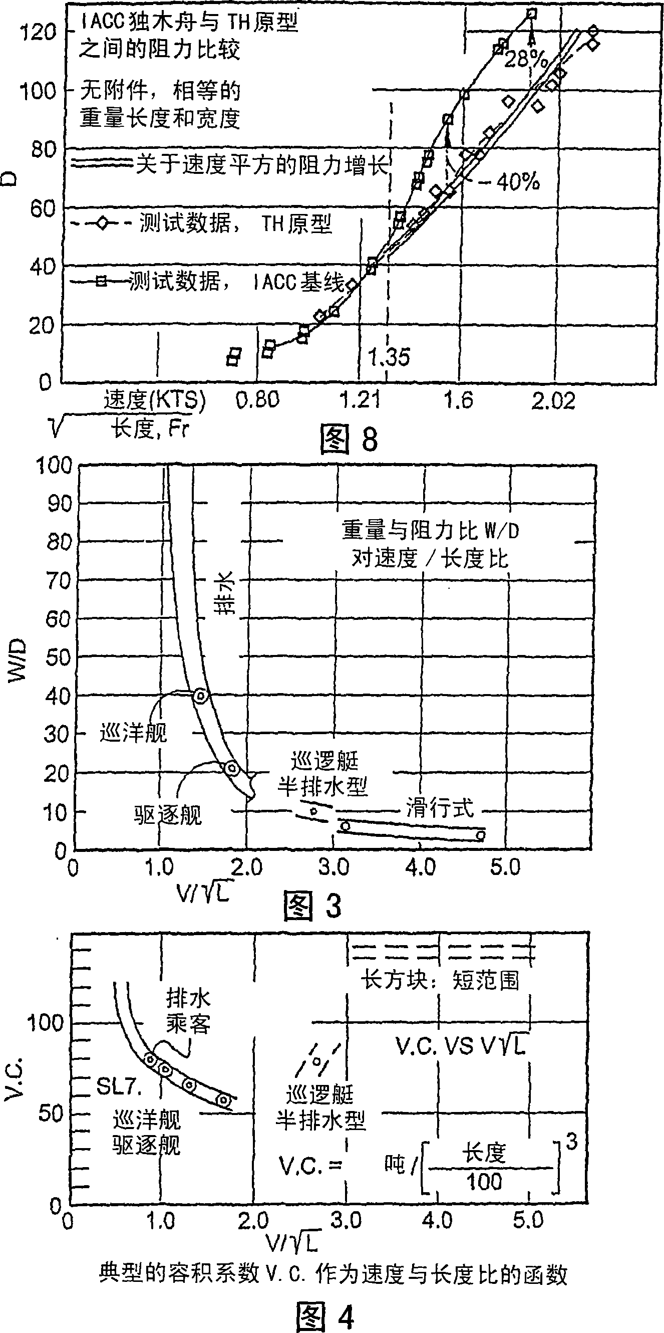
[0027] The nature and potential of the present invention can be better understood by examining the main characteristics of conventional hulls and examining the limitations and potential of transonic hull THs and their hydrofields in patent applications 08 / 814.418 and 08 / 814.417 range, where said conventional hulls have certain serious inherent problems in still water and adverse sea waves, all of which present the conceptual problems addressed by the present invention.

[0028] 1. Characteristics and problems of traditional hulls.

[0029] For this investigation it is necessary to differentiate conventional hull designs by hull type according to their operational speedenvelope. The envelopes of the various hull types expressed in terms of weight to drag ratios as a function of speed to length ratio are best considered together with their corresponding volume coefficients expressed in response to their velocity envelopes Longitudinal surface and volume distribution.

[0030] ...


PUM


Abstract

A transonic hull includes a bow, a stern, a longitudinal length therebetween, side surfaces extending from the bow to outboard portions of the stern, a lower surface extending between the side surfaces, the transonic hull having a submerged volume with an approximately triangular shape in planview with apex adjacent the bow and a base adjacent the stern, and an approximately triangular shape in side view when in motion with a base adjacent the bow and an apex adjacent the stern.

Description

technical field [0001] The present invention relates to water-supported watercraft such as commercial and military vessels, submarines, speedboats, the hulls of seaplanes for use with and out of surface effects, and watercraft in general, including navigating at high speeds in adverse sea waves of these ships. Background technique [0002] Technology related to this application may relate to technology in Jane's High Speed ​​Marine Craft. In addition, techniques relevant to this application may include transonic hull (TH) and transonic fluid fields ( TH ), and the propulsion, control and shape of the transonic hull as specified in patent application 08 / 814,417. [0003] Although certain vessels having a triangular hull plan shape apparently similar to TH's in some respects have been produced in the past (for example, as cited by the Patent Office during the prosecution of application 08 / 814,418), as conventional vessel designs , these vessels have been designed to have ap...

Claims


Application Information

Patent Timeline
IPC IPC(8): B63B1/06B63B1/16
CPCB63B2001/066B63B1/06B63B1/16Y02T70/126Y02T70/10
Inventor 阿尔伯特·阿尔瓦雷斯-卡尔德伦
Owner 阿尔伯特·阿尔瓦雷斯-卡尔德伦
Learn More