Supercharge Your Innovation With Domain-Expert AI Agents!

Locking mechanism for electric appliance

A technology of locking mechanism and tripping mechanism, applied in the direction of protection switch operation/release mechanism, circuit, electric switch, etc. The effect of small complexity

Inactive Publication Date: 2007-07-04
HAGER ELECTRO SAS
View PDF0 Cites 1 Cited by
  • Summary
  • Abstract
  • Description
  • Claims
  • Application Information

AI Technical Summary

Problems solved by technology

[0005] Known solutions with springs in the active part of the catch make these systems more complex and therefore more expensive to manufacture and install

Method used


Image

  • Locking mechanism for electric appliance
  • Locking mechanism for electric appliance
  • Locking mechanism for electric appliance

Examples


Embodiment Construction

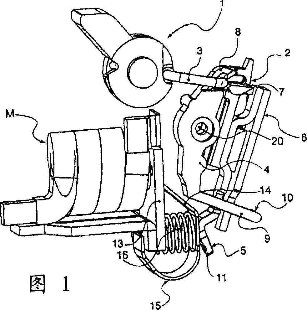
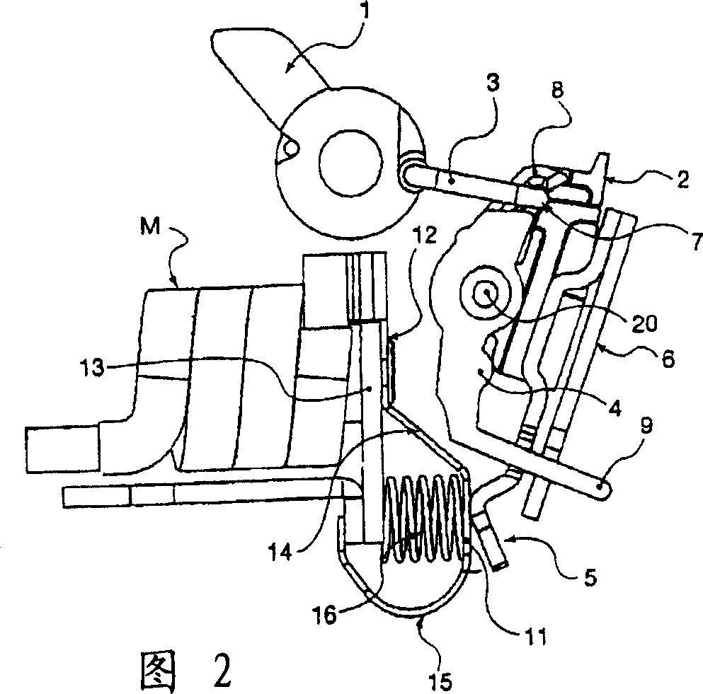
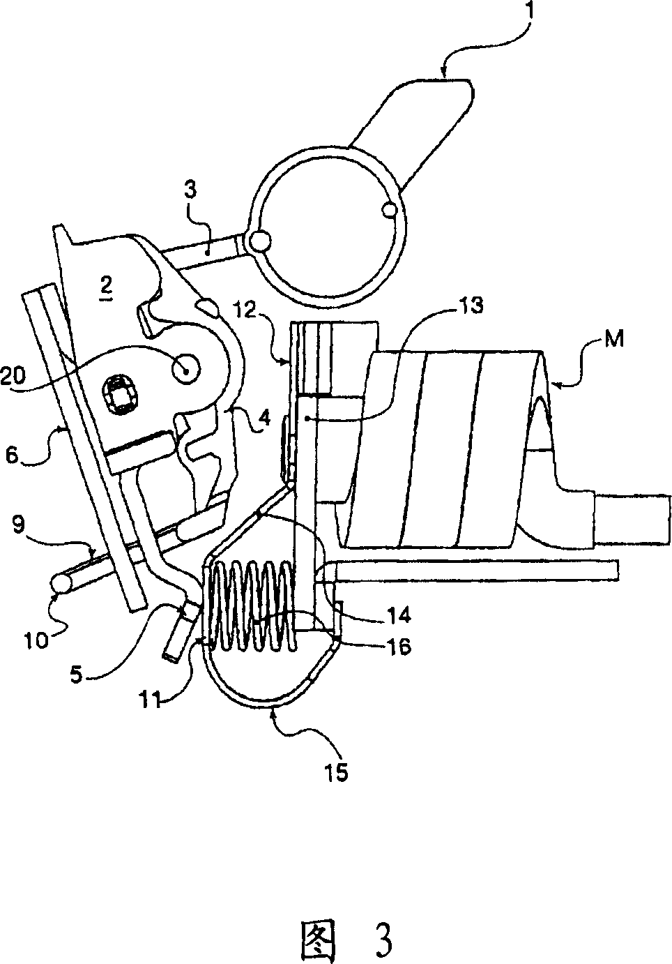
[0031] As shown in the figure, the control mechanism of an electrical appliance, such as a differential circuit breaker or a differential switch, is composed of a joystick 1 that is freely rotatable relative to the junction box of the electrical appliance, and its rotational movement is transmitted through a connecting rod 3 to a A movable component of the contact base 2.

[0032] The contact holder 2 itself is free to rotate about an axis relative to the junction box of the electrical appliance (not shown), and in the event of an abnormal operation of the circuit on which said electrical appliance is installed, a tripping mechanism 4 comes into play, also pivoting about said axis .

[0033] A movable contact 5 is fixed rigidly to the contact base 2 . According to one possibility, a bimetallic element 6 is also fixed rigidly to said movable contact 5 .

[0034] In general, it is known that the assembly works as a crank linkage in such a way that when the control mechanism 1 ...


PUM


Abstract

The present invention relates to a latching device, connecting to at least a pair of fixed contacts and traveling contacts, used in the differential breaker of protective circuit or differential switch electric appliance, transfers the motion of a control mechanism to each traveling contact, which is moved, supported on a pair of fixed contacts with a distance from the fixed contacts, and then obtaining the two stable states turn on / off by pressure contact. Therefor, the latching device is provided with a contact holder free rotating relative to the terminal box of electric apparatus and a tripping device for driving the contact holder which is in the off position of contact point. Each travelling contact is fixed in the contact holder rigidly, and each fixed contact is provided with a flexible assembly changing the contact force.

Description

technical field [0001] The present invention relates to a latching mechanism, connected to at least one pair of fixed and movable contacts, for the protection of circuits and personnel in appliances of the differential circuit breaker or differential switch type, or in general, for Any type of electrical appliance suitable for making and breaking an electrical circuit. Background technique [0002] In this type of electrical appliances, the locking mechanism is used in particular to transmit the movement of a control mechanism of the joystick type to each movable contact, which is supported on a corresponding fixed contact and connected to said fixed contact. The contacts are separated by a certain distance to obtain two stable states of pressure contact connection and line disconnection. Traditionally, this mechanism has a contact seat and a tripping mechanism, the contact seat is free to rotate relative to the junction box of the electrical appliance, and the function of ...

Claims


Application Information

Patent Timeline
Patent Type & Authority Applications(China)
IPC IPC(8): H01H71/10H01H71/12H01H71/50
CPCH01H71/526H01H1/26H01H71/40H01H1/502
Inventor 丹尼斯·赫布雷克
Owner HAGER ELECTRO SAS
Features
  • R&D
  • Intellectual Property
  • Life Sciences
  • Materials
  • Tech Scout
  • Unparalleled Data Quality
  • Higher Quality Content
  • 60% Fewer Hallucinations
Learn More