Lower entry lower exit spiral type conveyer

A conveyor and screw type technology, which is applied in the field of bottom-in and bottom-out screw conveyors, can solve the problems of increasing the installation of conveyors, gear sets with 13 large loads, and reducing the installation space of screw conveyors.

Inactive Publication Date: 2007-07-11
李信宏
View PDF0 Cites 2 Cited by
  • Summary
  • Abstract
  • Description
  • Claims
  • Application Information

AI Technical Summary

Problems solved by technology

[0004] However, the current spiral conveying equipment is based on the direction of the spiral, so the feeding and discharging generally adopts a low (feeding) and high (discharging) method, and the material is fed from a low place so that the material passes through the spiral conveyor belt. 10 conveying to a higher position, and then another conveying device 14 to send the material down from a high place. Since the conveying device 14 must have an appropriate inclination to convey the material safely and stably, the setting of the conveying device 14 is The installation space of the conveyor is increased, and the installation space of the spiral conveyor can be reduced.
In addition, the spiral conveying equipment provides the movement of the conveyor belt 10 to be driven by the transmission motor 12 at one end of the gear set 13. However, when the conveyor belt 10 is in a spiral winding state, the conveyor belt 10 will move in a curved line. The frictional resistance with the frame 11 will cause the gear set 13 itself to cause a large load, and the transmission motor 12 needs to provide a large power source, and it may increase the probability of damage to the mechanical parts during the future movement.

Method used


Image

  • Lower entry lower exit spiral type conveyer
  • Lower entry lower exit spiral type conveyer
  • Lower entry lower exit spiral type conveyer

Examples


Embodiment Construction

[0024] Relevant technical means and structural feature thereof that the present invention utilizes for reaching the purpose, cooperate the preferred embodiment shown in accompanying drawing again hereby, describe in detail as follows:

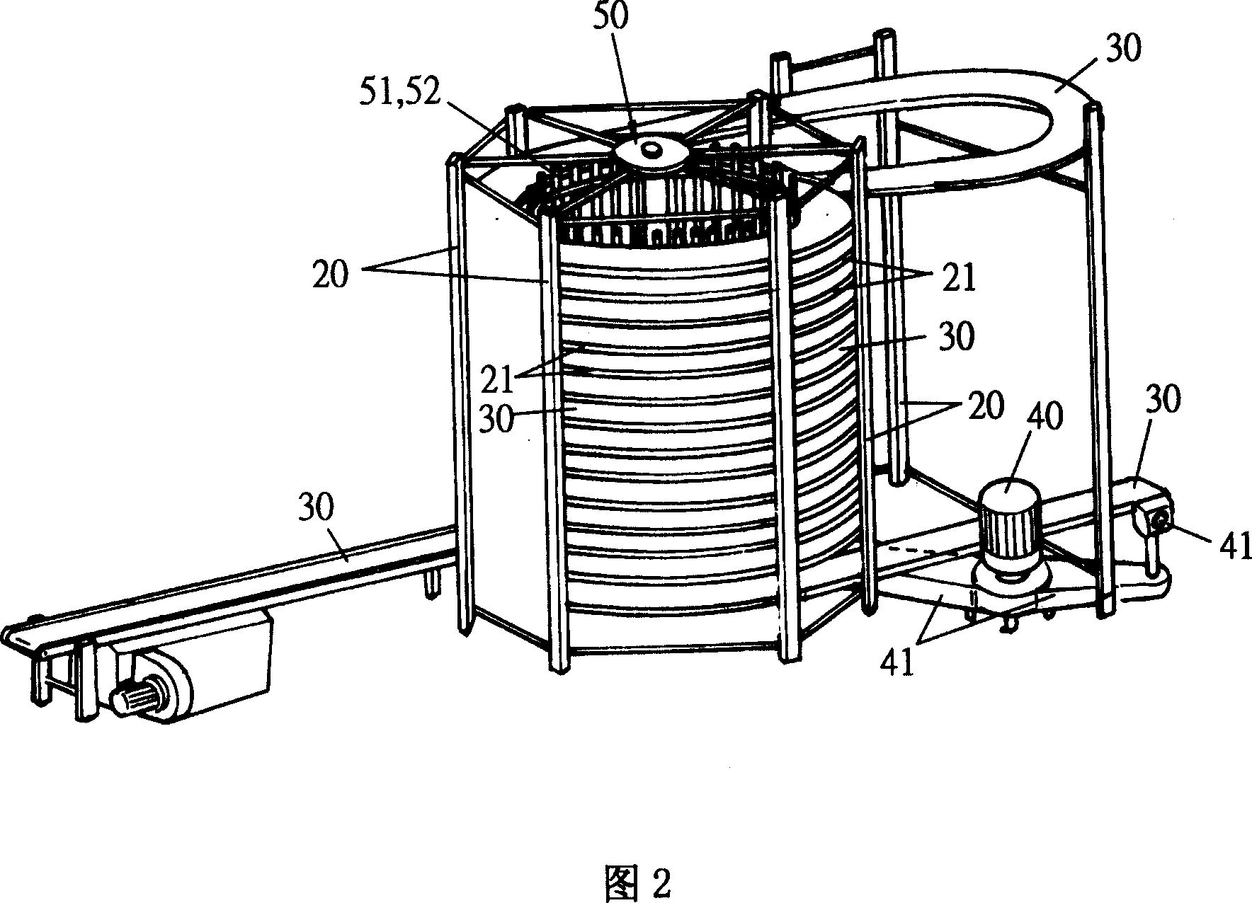
[0025] Please refer to Fig. 2, the present invention mainly comprises skeleton body 20, conveyer belt 30, transmission machine 40 and auxiliary transmission device 50 and constitutes; Wherein:

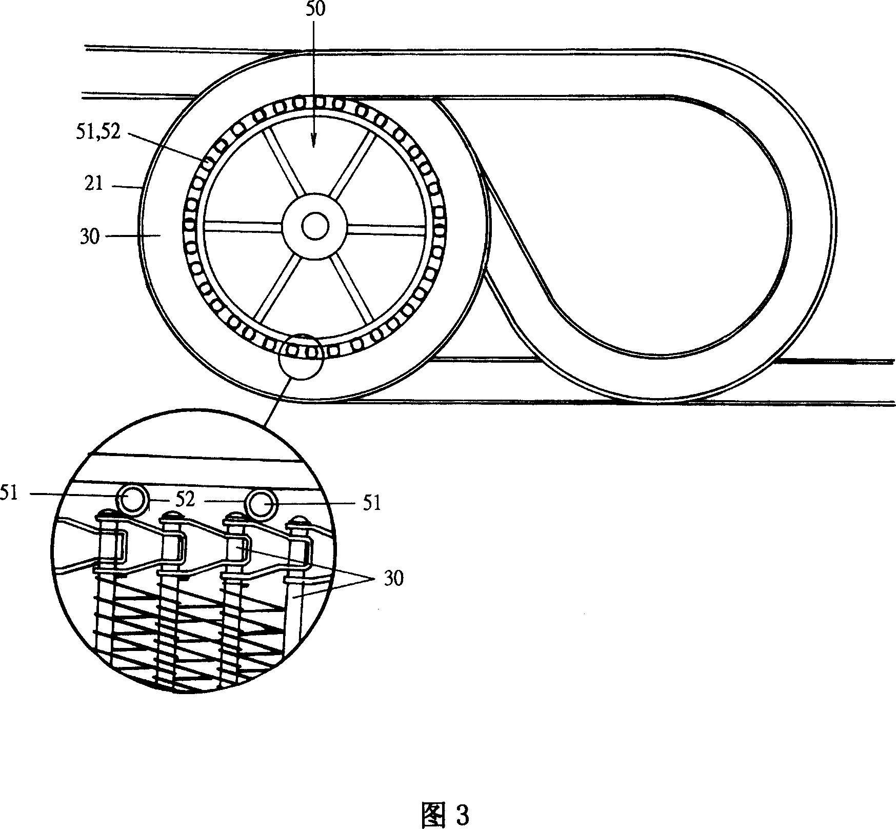
[0026] Please refer to Figures 3 and 4 again, the skeleton body 20 is a frame made of metal skeleton, in which a spiral orbit 21 is erected, and the orbiting method is to start from the bottom, go up to the top, and then criss-cross. The way goes down to the end point, the track 21 can be used for the conveyor belt 30 to bear on it, and then the transmission 40 drives the gear set 41 to make the conveyor belt 30 move on the track 21; please refer to Figures 5 and 6, the The auxiliary transmission device 50 is arranged upright by several brackets 51 to f...


PUM


Abstract

The invention relates to a low-in low-out screw transmitter, wherein it is formed by main body, transmission band, transmitter and assist transmitter. The main body has screw track whose lower point is initial point, screwing to the top end and alternated to the lower final point; said track can support the transmission band; transmitter drives the gear group to move the transmission band on track; the assist transmitter is formed by several upright supports into cylinder; each support has several distanced muffles; the muffle can rotate freely on the support; the assist transmitter is at the inner side of transmission band, to approach the muffle with the inner edge of transmission band; the assist transmitter can rotate along with the transmitter; the transmission band transfers material at lower part; the support of assist transmitter can move the transmission band.

Description

technical field [0001] The invention relates to a bottom-in and bottom-out screw conveyor, especially a conveyor belt installed in a spiral manner, which advances and discharges from the bottom, so that it can not only save the installation space of the conveyor, but also provide more Labor-saving and smooth conveyor structure. Background technique [0002] The conveying mode of the traditional conveyor is generally a linear motion. For processing with a long process, this type of conveyor needs to be installed in a large area of ​​work space, and the additional equipment installed on the conveyor is also relatively large. Increase; for example, frozen food, bakery products, etc. made by consistent operations must have a long conveying distance to obtain the necessary processing time, and must maintain a certain operating temperature within the conveying range. Therefore, the conveyor's The installation occupies a large plane space, and the transportation process of the con...

Claims


Application Information

Patent Timeline
Patent Type & Authority Applications(China)
IPC IPC(8): B65G15/00B65G15/60B65G21/22B65G41/00
Inventor 李信宏
Owner 李信宏
Why Eureka
Try Eureka