Elevator guide rail error checking system and method

A technology of error detection and elevator guide rails, applied in the field of elevators, can solve problems such as unsafe, error detection guide rails, coordinates cannot be reflected intuitively, and achieve the effect of avoiding offset and improving detection accuracy

Active Publication Date: 2007-07-11
HITACHI ELEVATOR CHINA
View PDF1 Cites 16 Cited by
  • Summary
  • Abstract
  • Description
  • Claims
  • Application Information

AI Technical Summary

Problems solved by technology

[0003] 1. The length of the calibration ruler and the clamping plate is longer than the distance between the guide rails, and the operation of the error detection guide rail is inconvenient due to its length when working in the hoistway;
[0004] 2. In the error detection of the opposite direction of the guide rail, the error is relatively large;
[0005] 3. With the need to expand the space of the building upwards, it has become a trend for elevators to develop towards high-rise and high-speed directions. It is extremely unsafe to use a calibration ruler and a pallet for error detection.
[0006] In order to improve the accuracy and convenience of error detection of elevator guide rails, new methods have emerged to detect the errors of elevator guide rails. For example, in Chinese patent 02149218.2, an "inclination sensor" is used to detect the verticality of guide rails; meanwhile, by The position coordinates of each detection point detected by the "displacement sensor" are not real position coordinates. The coordinates of each detection point on the guide rail cannot be reflected intuitively, and the inspector cannot intuitively know the theoretical value of each detection point on the guide rail. deviation between

Method used


Image

  • Elevator guide rail error checking system and method
  • Elevator guide rail error checking system and method
  • Elevator guide rail error checking system and method

Examples


Embodiment 1

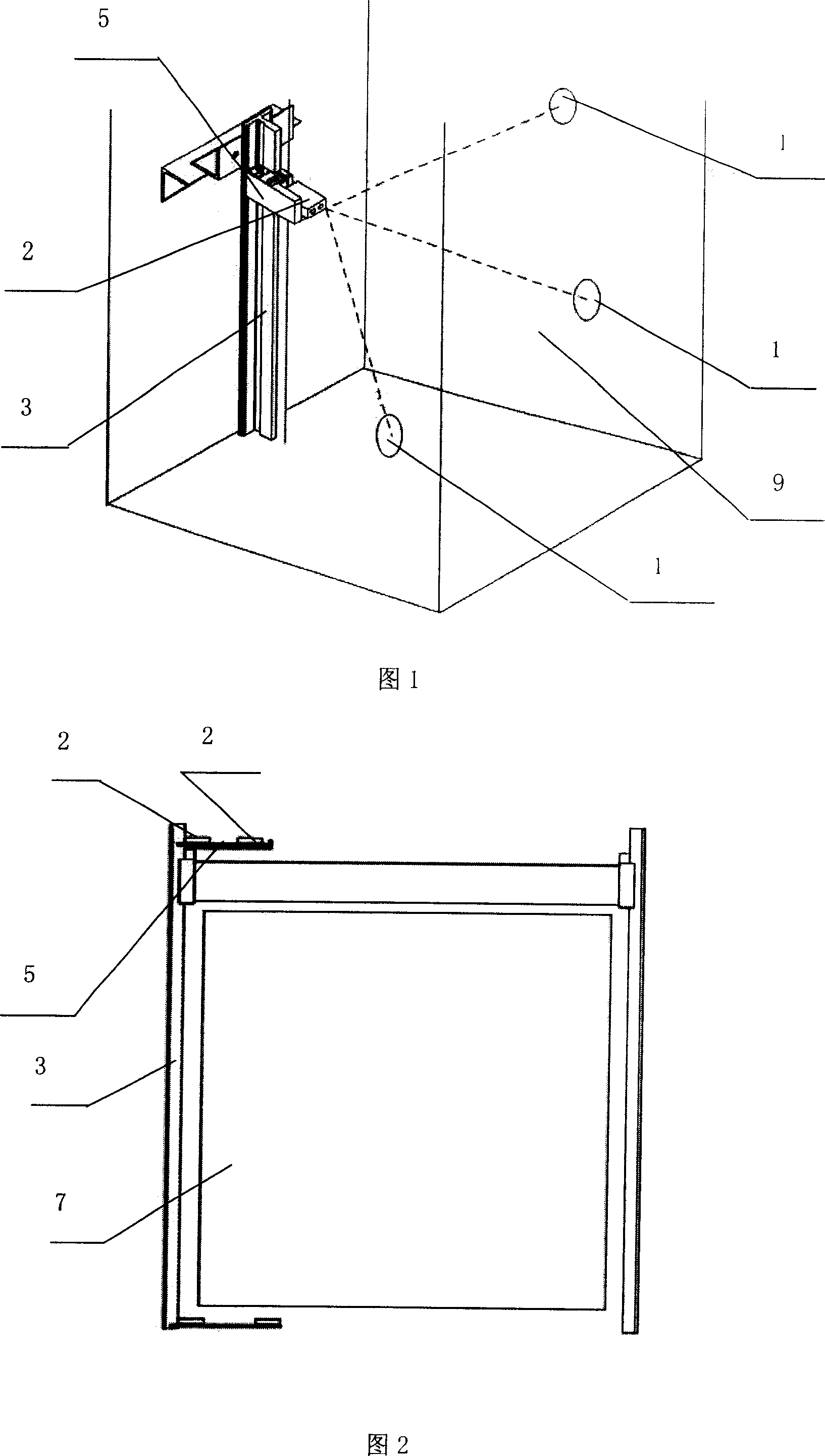
[0047] Please refer to Fig. 1 to Fig. 4, an elevator guide rail error detection system, the error detection system includes: three ranging signal transmitters 1 in different positions, and the three ranging signal transmitters 1 respectively send out different ranging signals ; The ranging signal receiving device 2 cooperating with the ranging signal transmitting device 1 ; The signal processing device for processing the data of the ranging signal receiving device 2 ; The result output device.

[0048] The distance-measuring signal transmitter 1 (being an ultrasonic transmitter) is fixed in the shaft 9, and the plane where the connection lines of the three distance-measurement signal transmitters 1 are at an inclined angle to the horizontal plane and the vertical plane (that is, the three distance-measuring signal transmitters The plane where the connection line of the device is located is a non-horizontal plane (non-vertical plane); there are two ranging signal receiving devic...

Embodiment 2

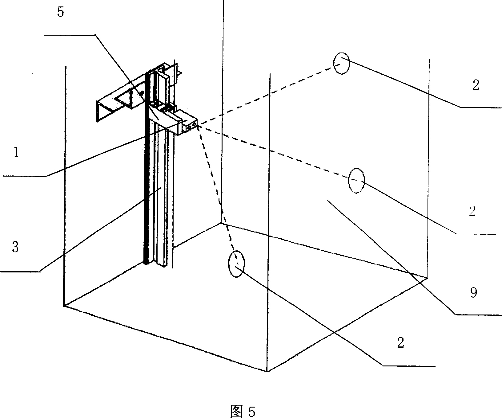
[0056] Please refer to Fig. 5, the difference between this embodiment and Embodiment 1 is that in this implementation, the ranging signal receiving device 2 is fixed in the hoistway 9, and the ranging signal transmitting device 1 is connected to the car 7 through the bracket 5 , on the bracket 5 there is a guide rail slot 6 matching with the guide rail 3; the ranging signal transmitting device 1 can slide on the guide rail 3. The working principle of this embodiment is the same as that of the first embodiment, except that the distance-measuring signal transmitting device 1 and the distance-measuring signal receiving device 2 are arranged in different positions.


PUM


Abstract

The invention relates to a lifter track error detector and relative method, wherein system comprises that: three ranging signal emitter at different positions; ranging signal receiver; signal processor for treating received data; result output device. One of ranging signal emitters is fixed in well, while another two can slide on track. And the method comprises that: ranging signal emitters emit signals; receiver receives the ranging signal, to calculate out the distance between emitting point and receiving point, to find the coordinate of one point; sliding the emitters along track, calculating out the coordinate of each point; calculating out the processing error or mounting error of track.

Description

technical field [0001] The invention relates to the field of elevators, in particular to an elevator guide rail error detection system and method. Background technique [0002] During the operation of the vertical elevator, the position of the car is guided by the guide rail. If there is a deviation in the manufacture or installation of the guide rail, it will cause the car to swing or misalign during operation. Therefore, the position accuracy of the guide rail ( Such as verticality) directly affects the safety of the elevator. However, the guide rail error detection of existing vertical elevators mostly uses mechanical rail alignment rulers and pallets. This method of rail calibration ruler and pallet error detection methods has the following deficiencies: [0003] 1. The length of the calibration ruler and the clamping plate is longer than the distance between the guide rails, and the operation of the error detection guide rail is inconvenient due to its length when work...

Claims


Application Information

Patent Timeline
Patent Type & Authority Applications(China)
IPC IPC(8): B66B5/00G01B21/22G01S15/08G01S17/08
Inventor 周云翔林汉洁邓忠英
Owner HITACHI ELEVATOR CHINA
Why Eureka
Try Eureka