
Cloth-feeding device of sewing machine

A cloth feeding device and sewing machine technology, which is applied in the direction of sewing machine control devices, sewing machine components, sewing machine needle seats, etc., can solve the problems of inability to increase the speed, decrease in the quality of sewing products, and inconsistent feeding volume, and achieve the sewing pitch roughly the same effect

Inactive Publication Date: 2007-07-11
JUKI CORP
View PDF1 Cites 16 Cited by
  • Summary
  • Abstract
  • Description
  • Claims
  • Application Information

AI Technical Summary

Problems solved by technology

This difference is the difference in the horizontal position of the pierced cloth, which will cause a situation that does not match the cloth feeding amount set by the turntable 119.
Especially in the case where the thickness of the fabric is obviously different in a series of sewing (such as the shoulder pad sewing of a suit), it will lead to the difference in the sewing spacing in one process, which will reduce the quality of the sewing product
[0007] As a solution to such a problem in needle feeding, there is a method of using a triangular cam to form the cloth feeding cam 102, so that the trajectory of the needle tip can be approximated to a rectangle, thereby preventing the difference in the distance between sewing due to the influence of the thickness of the cloth. method, but there are problems such as large acceleration and deceleration on the mechanism, inability to increase the speed, and increased noise and vibration

Method used


Image

  • Cloth-feeding device of sewing machine
  • Cloth-feeding device of sewing machine
  • Cloth-feeding device of sewing machine

Examples


Embodiment Construction

[0023] Next, the best mode of the cloth feed device of the sewing machine will be described in detail with reference to the drawings.

[0024]

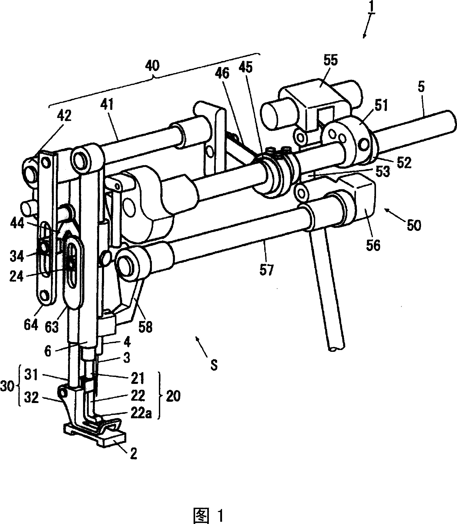
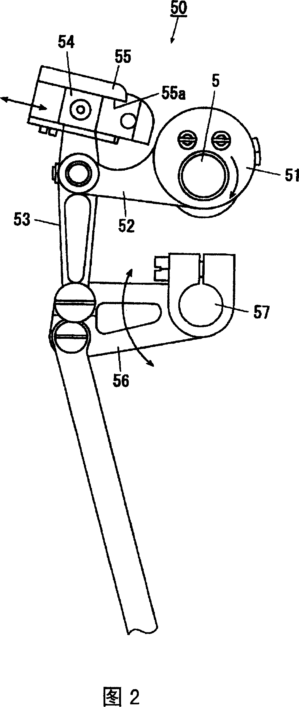
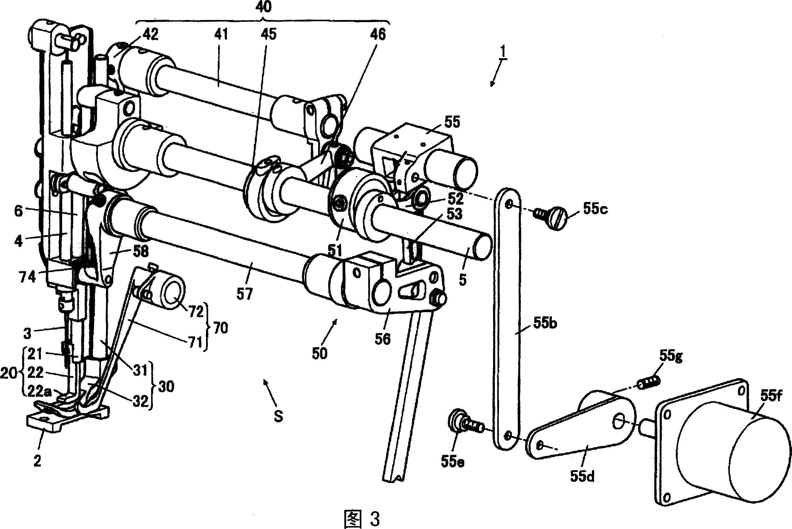
[0025] As shown in FIGS. 1 to 4 , the cloth feeding device 1 of the sewing machine has an upper cloth feeding part 20 that moves in the cloth feeding direction in a state of contacting the cloth as the sewing object on the needle plate 2 from above to perform cloth feeding. The conveying of the cloth; the cloth pressing part 30, which has a presser foot 32 that presses the cloth toward the needle plate 2 from above; Carry out the reciprocating action in the up and down direction; the second action mechanism 50 (needle feeding mechanism, referring to Fig. 3 ), it makes the upper cloth feeding part 20 carry out the reciprocating action on the cloth feeding direction; When the cloth part 20 and the cloth pressing part 30 respectively descend, by abutting against them from below, the respective lower limit positions are determined, and ...


PUM


Abstract

The present invention provides a fabric feeding apparatus of sewing machine capable of providing approximately same distance of sewing. The fabric feeding apparatus of sewing machine comprises a fabric frame (S), which moves synchronously with a needle bar (4) moving up and down driven by a motor of the sewing machine, and feeds fabric on a needle plate (2) by feeding tooth; a fabric feeding quantity input apparatus, which inputs fabric feeding quantity based on the fabric frame (S); a drive control apparatus (70), which measures fabric thickness fed by the fabric frame (S); a storing apparatus, which stores fabric feeding quantity translation table of relationship between fabric thickness and fabric feeding quantity suiting for the fabric thickness; and a fabric feeding quantity correction apparatus, which selects the fabric feeding quantity corresponding with fabric thickness measured by the drive control apparatus (70) from the fabric feeding quantity translation table and corrects the data of fabric feeding quantity with the fabric feeding quantity input apparatus such that the fabric feeding quantity is that selected.

Description

technical field [0001] The present invention relates to a cloth feeding device of a sewing machine such as a needle feeding sewing machine or a combined feeding sewing machine having a needle feeding function of moving a cloth by oscillating a needle. Background technique [0002] As the above-mentioned combined feed sewing machine, there is known, for example, a sewing machine described in JP-A-7-136363. Referring to FIGS. 6 and 7 to describe a conventional combined feed sewing machine, the main shaft 101 is connected to a sewing machine motor (not shown) that serves as a driving source for sewing, and is driven to rotate around the axis by the sewing machine motor. A feed cam 102 composed of an eccentric cam is provided on the main shaft 101. A rod 103 that swings up and down by the rotation of the feed cam 102 is connected to the feed cam 102. The needle 125 and the upper feed leg 126 swing the lever 104 in the horizontal direction, and the lever 127 swings the lower fee...

Claims


Application Information

Patent Timeline
Patent Type & Authority Applications(China)
IPC IPC(8): D05B27/00D05B55/00D05B29/06D05B19/12D05B69/00
CPCD05B19/16D05B27/04
Inventor 佐藤正彦
Owner JUKI CORP
Learn More