
Brushless DC motor control device and control method therefor

A brushed DC motor and control method technology, which is applied in the direction of AC motor control, DC motor speed/torque control, motor control, etc., can solve the problems of limiting the maximum power of the motor, not suitable for the miniaturized design of the motor, and rising manufacturing costs.

Inactive Publication Date: 2007-07-11
SAMSUNG ELECTRONICS CO LTD
View PDF0 Cites 14 Cited by
  • Summary
  • Abstract
  • Description
  • Claims
  • Application Information

AI Technical Summary

Problems solved by technology

[0006] However, at present, in order to prevent the permanent magnet from demagnetizing at low temperature, when the overcurrent limit value is set according to the low temperature condition of the brushless DC motor, since the overcurrent limit value is fixed at a certain value, although the low temperature condition of the motor can be carried out under low temperature The demagnetization protection works, but it also limits the maximum power of the system when it is operated at room temperature except for low temperature conditions.
That is, since the maximum load current of the brushless DC motor is limited by the low-temperature demagnetization characteristics of the permanent magnets used to form the rotor, the result is that the maximum power of the motor must be limited
Ultimately, limiting the operable range of BLDC motors
[0007] To overcome the above problems by improving the design specifications of the motor, it is necessary to reduce the load current by improving the efficiency of the brushless DC motor, but this design change of the motor not only increases the manufacturing cost, but also is not suitable for the miniaturization design of the motor

Method used


Image

  • Brushless DC motor control device and control method therefor
  • Brushless DC motor control device and control method therefor

Examples


Embodiment Construction

[0020] Hereinafter, preferred embodiments of the present invention will be described in detail with reference to the drawings.

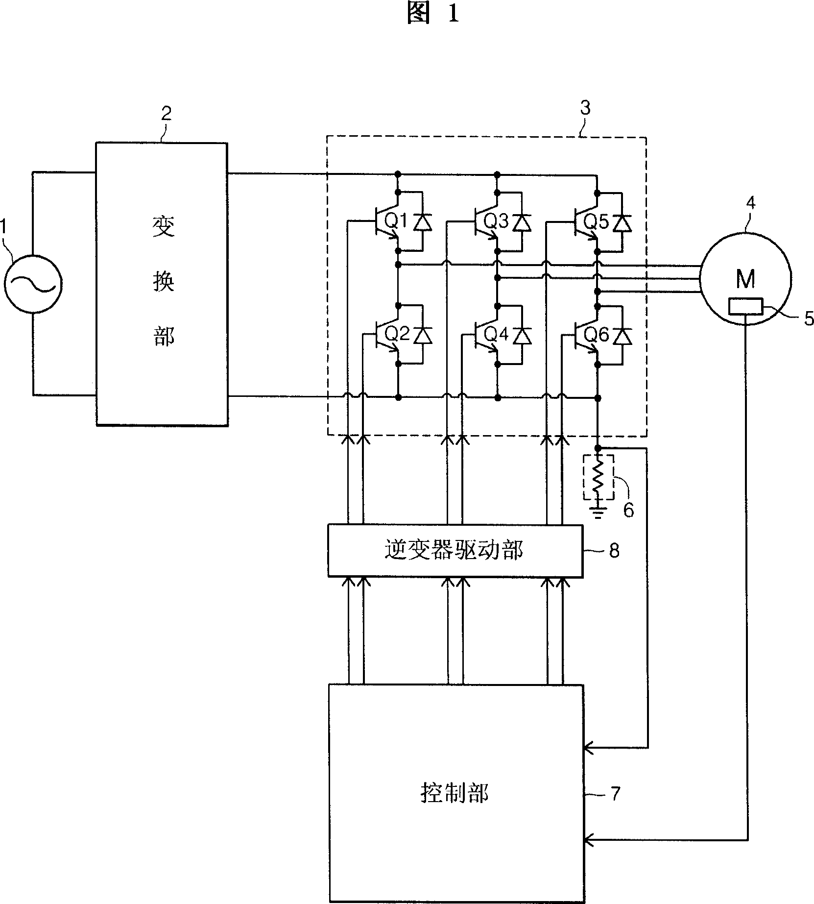
[0021] As shown in Figure 1, the control device of the brushless DC motor 4 provided according to the present invention includes: an AC power supply 1; a converter 2 for converting the AC power of the AC power supply 1 into DC power; The inverter 3 that converts the DC power of the device 2 into AC power; the brushless DC motor 4 driven by the inverter 3; the current detection part 6 for detecting the load current of the brushless DC motor 4; The inverter driving part 8 of the inverter 3; the control part 7 controls the inverter by outputting a control signal for controlling the rotation speed of the brushless DC motor 4 to the inverter driving part 8 according to the current value detected by the current detecting part 6. Transformer.

[0022] The inverter 3 is composed of a plurality of transistors (Q1 to Q6), and the plurality of transistors (Q1 ...


PUM


Abstract

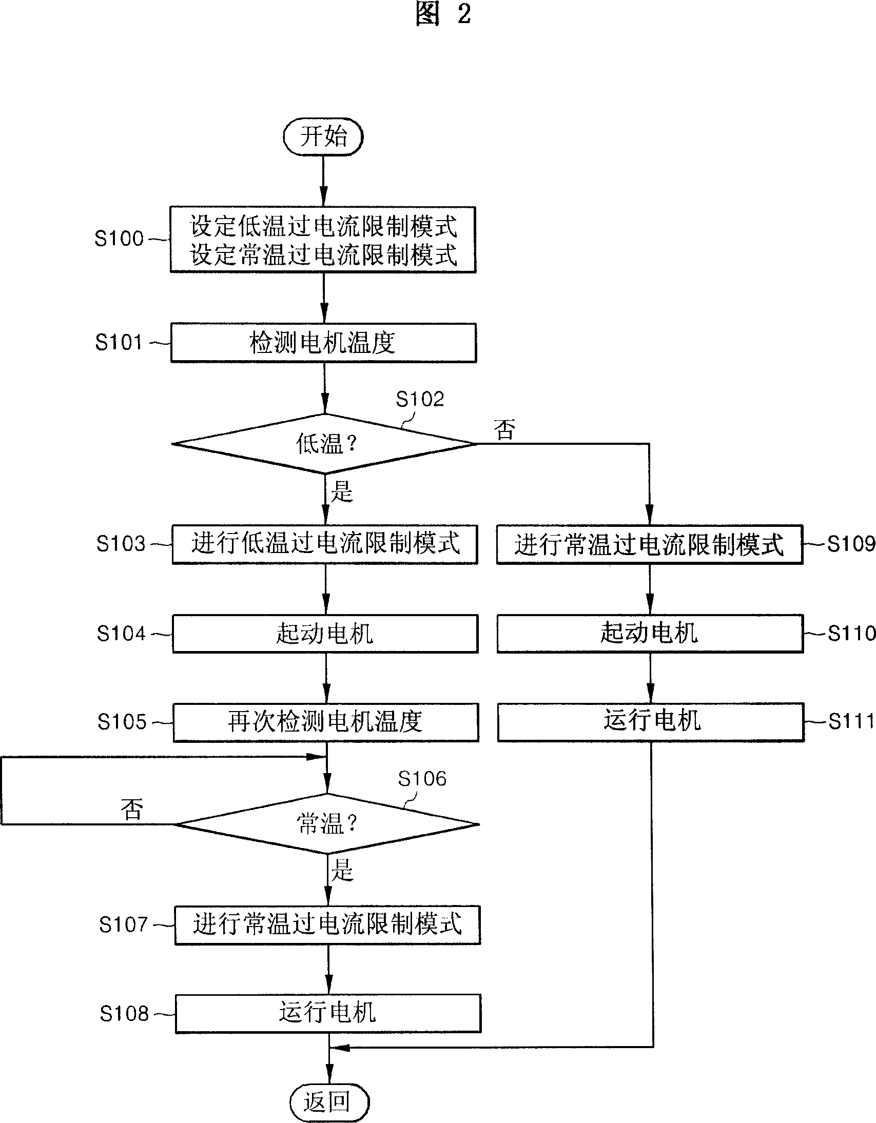
The present relates to a control device for brushless DC motor and control method thereof, especially relates to altering overcurrent upper limit value into corresponding value by monitoring operation conditions of brushless DC motor at low or normal temperature and according to each operation conditions, thus when the operation condition of the motor is at low temperature, overcurrent upper limit value is correspondingly reduced to protect demagnetization of the permanent magnet, when the operation condition switches into normal temperature, maximum power of the motor can be ensured by correspondingly improving the overcurrent upper limit value.

Description

technical field [0001] The invention relates to a control device and a control method of a brushless direct current motor, in particular to a control device and a control method of the brushless direct current motor which can effectively prevent the low-temperature demagnetization of the rotor permanent magnet of the brushless direct current motor. Background technique [0002] Generally, a high-efficiency, low-noise brushless DC motor is generally used to drive an outdoor fan of an air conditioner. This brushless DC motor has a stator composed of three-phase windings and a rotor composed of permanent magnets. [0003] The permanent magnets that make up the rotor of a brushless DC motor are subject to low-temperature demagnetization. This phenomenon is caused by excessive demagnetization of the magnets due to the peak current of the armature coil when the motor is operating at low temperature. A phenomenon in which the magnetic force cannot be restored to the original magne...

Claims


Application Information

Patent Timeline
IPC IPC(8): H02P7/00H02H7/08
CPCH02P6/085H02P25/03H02P29/027H02P29/032H02P2207/05
Inventor 金振竖安钟吉
Owner SAMSUNG ELECTRONICS CO LTD
Learn More