Brushless Dc Motor Control Method and Brushless Dc Motor Controller

a brushless dc motor and control method technology, applied in the direction of electronic commutators, dynamo-electric converter control, heating types, etc., can solve the problems of excessive current burning down the motor, easy to make the wrong wiring, and the motor cannot be started, so as to reduce the quantity of wiring and reduce the complexity of wiring. , the effect of improving the seal of the motor

Inactive Publication Date: 2008-09-25
SANDEN HUAYU AUTOMOTIVE AIR CONDITIONING CO LTD +1
View PDF6 Cites 9 Cited by
  • Summary
  • Abstract
  • Description
  • Claims
  • Application Information

AI Technical Summary

Benefits of technology

[0046]By using the technique of the present invention, the position sensor is not needed and the wiring quantity and wiring complexity are decreased. The motor seal improves. M

Problems solved by technology

Due to its many and complexity of wiring, it is easy to make the wrong wiring.
The wrong wiring will induce that the motor can not be started and the excessive current will burn down the motor.
Meanwhile, the additional wiring is prohibitive to the seal for the compressor.
After long-term use of the motor, the position sensor will deviate and the efficiency of the motor will decrease dramatically.
In the worst case, the motor will loose its

Method used


Image

  • Brushless Dc Motor Control Method and Brushless Dc Motor Controller
  • Brushless Dc Motor Control Method and Brushless Dc Motor Controller
  • Brushless Dc Motor Control Method and Brushless Dc Motor Controller

Examples


Embodiment Construction

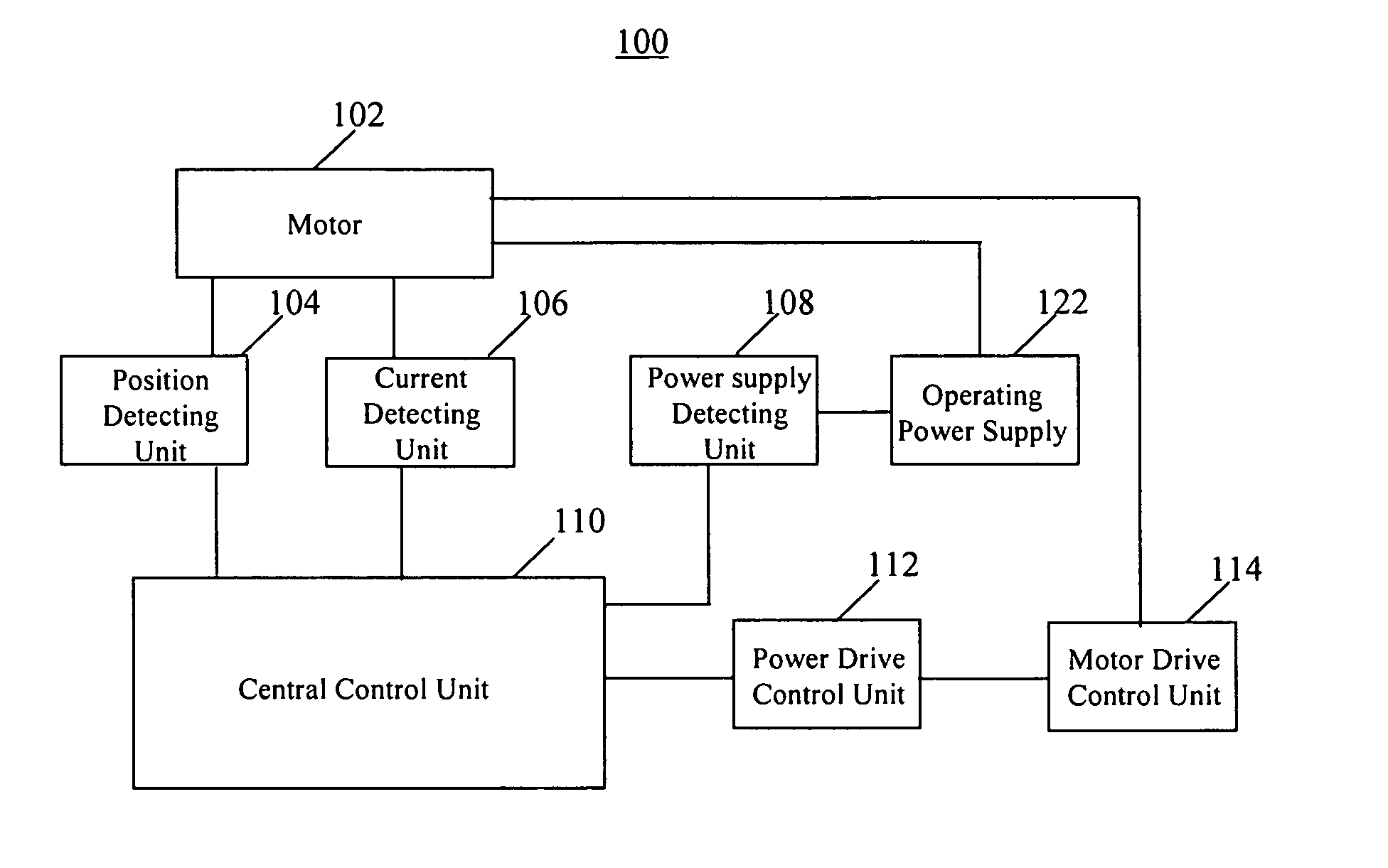
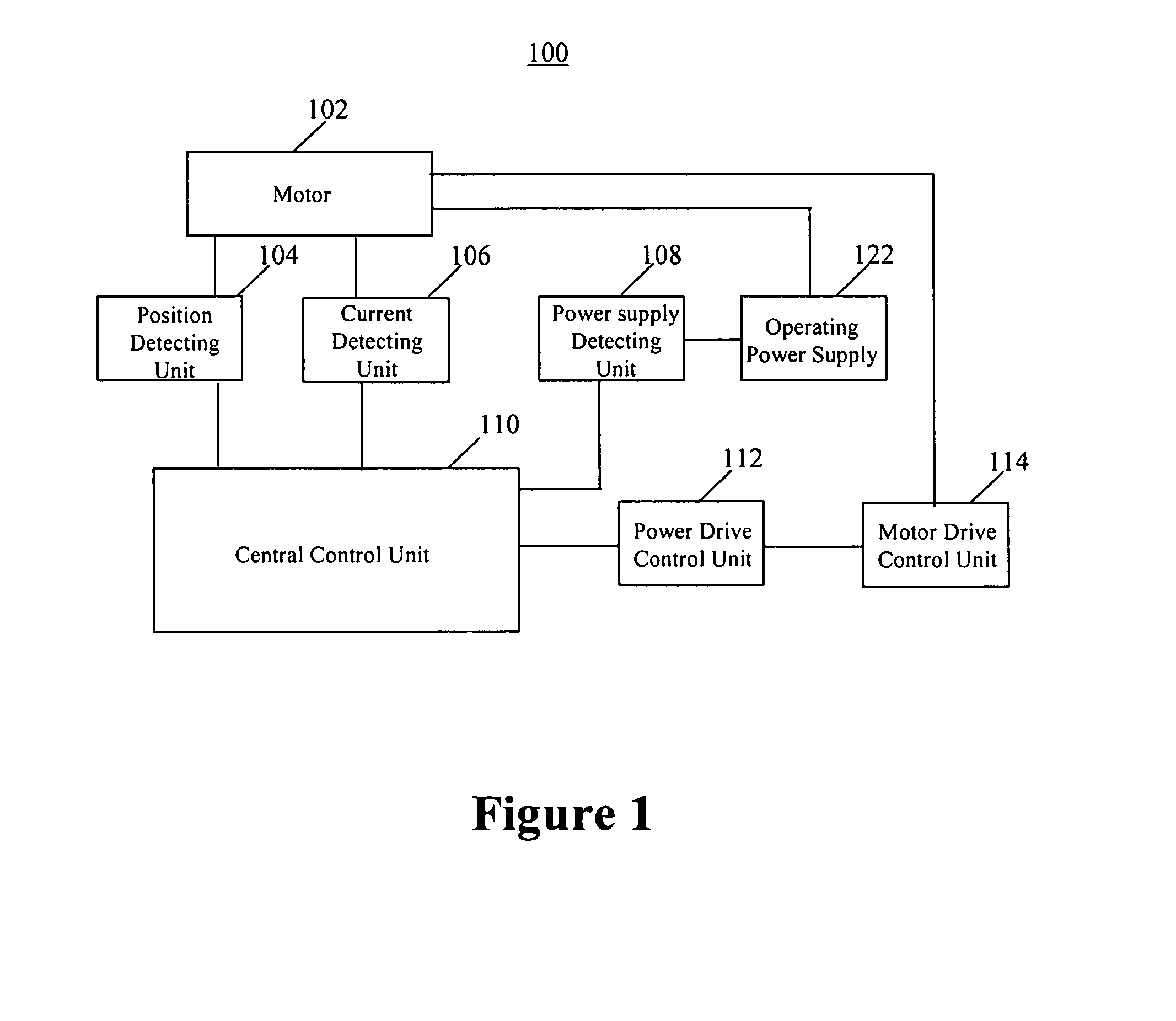
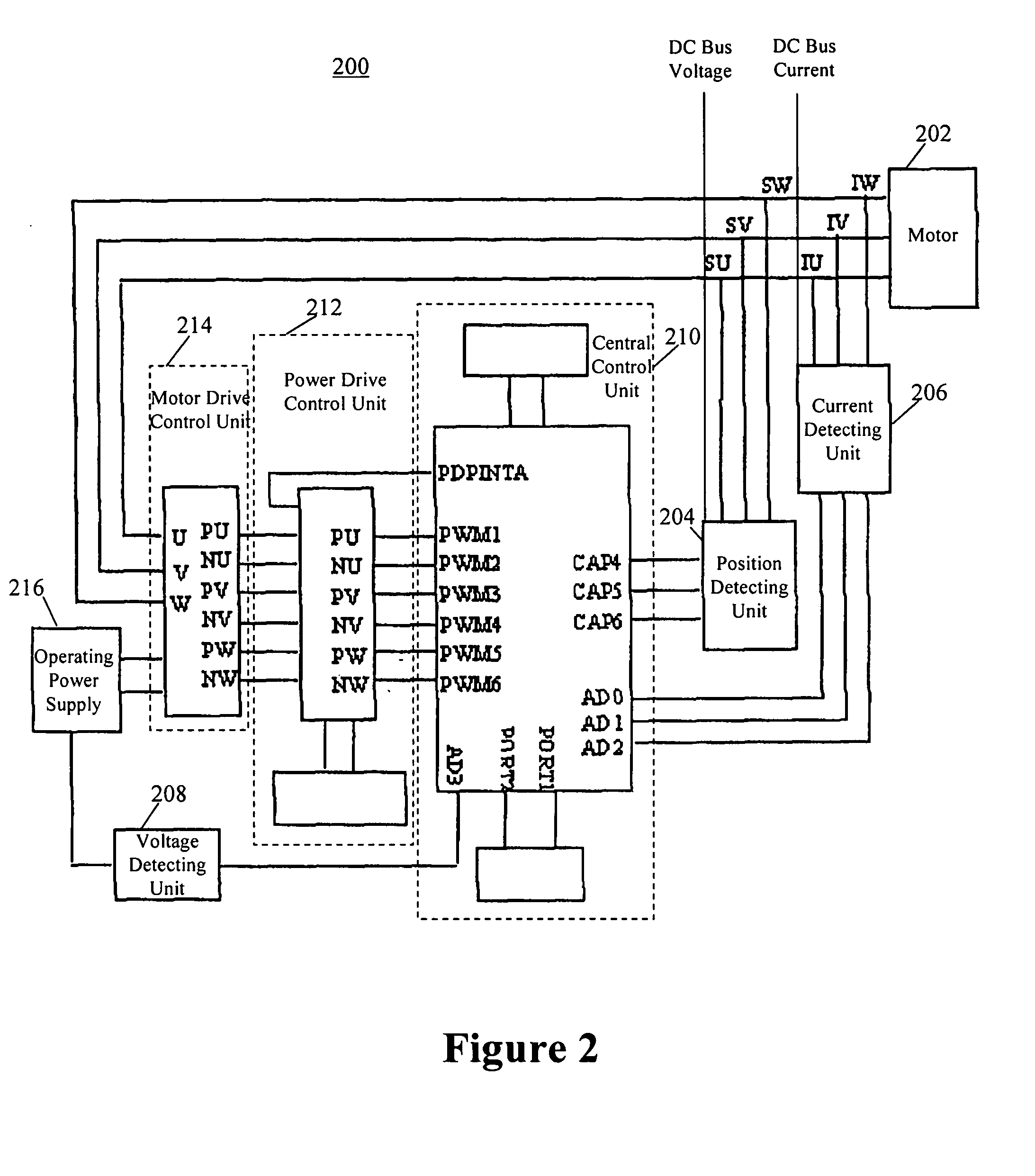
[0056]Referring now to the drawings attached which further illustrate the technical implementation of the invention.

[0057]Firstly the invention principle is explained. This invention builds the database of the motor running parameters, and then detects the signals pertinent to the rotor's running state such as the voltage and the current, finally after processing these signals obtains the signals about the rotor's position. For instance, the rotor's position is determined by detecting the motor's induced EMF. But in a real circumstance, especially in a circumstance with a high voltage and a large load, due to the disturbance signal the induced EMF detected appear the edge signals. If these edge signals are not eliminated, the rotor's position will be determined incorrectly. Thus the motor can not operate properly. Hence these detected signals should be filtered before being used. The best filter is the low-pass filter to cut out the high frequency components. The cut-off frequency o...


PUM


Abstract

The present invention discloses a control technology for brushless DC motor, in which firstly it is to build or import a motor running parameters' database, then detect the signals always running and the signals closely relevant to the rotor's rotating state such as the voltage and the current, and process these signals and figure out the signals about the rotor's position. Wherein these detected signals should be filtered before being used, and the best filter is the low-pass filter to cut out the high frequency components, and the cut-off frequency of the low-pass filter are determined by the motor running voltage U and PWM signal width when the motor is running at no load, finally determine if the motor is working properly by means of the motor running parameters stored in the database in advance, that is to determine if the detected value is identical with the one predicted from the database. Depending on the results from the detecting and comparison above, the control signal is generated to adjust the motor running state. With the technical method in this invention, the position sensor is not needed. This reduces the motor's external wiring amounts and the wiring complexity. Also the motor's seal is improved. Meanwhile, it is possible to measure the rotor's position accurately in any state according to this invention technology. Thus the motor running state can be controlled properly.

Description

CROSS REFERENCE OF RELATED APPLICATIONS[0001]The present application requests the priority of the Chinese application numbered 200310124504.6 and entitled “Air-condition Electric Compressor Controller”, being filed on Dec. 30, 2003. The application has been assigned to the assignee of this patent application and the whole documents are incorporated herein by reference.[0002]1. Field of Invention[0003]The invention relates to air-condition motor control technology. More particularly, refers to the controller for brushless DC motor without position sensor and the controlling method thereof.[0004]2. Background of Invention[0005]To start running a brushless DC motor comprises three sequences: the rotor locating, the forced synchronous accelerating run and the synchronous (switched) run. In this procedure, the testing of the motor rotor's position is important for the running control of motor. The commonly used technique is installing a position sensor based on Hall devices in the rotor ...

Claims


Application Information

Patent Timeline
IPC IPC(8): H02P6/18F24F11/02H02P6/08
CPCH02P6/18H02P6/08H02P6/181H02P6/182H02P6/34
Inventor ZHONG, MINXIANHE, BINYAO, XIAODONGZOU, JUNZHONG
Owner SANDEN HUAYU AUTOMOTIVE AIR CONDITIONING CO LTD
Why Eureka
Try Eureka