
Chronograph

a chronograph and rotor technology, applied in the field of chronographs, can solve the problems that the balance wheel would stop moving, etc., and achieve the effect of reducing frictional loss, optimal pulse transmission, and reducing frictional loss

Active Publication Date: 2018-06-19
HEINZ UWE
View PDF15 Cites 0 Cited by
  • Summary
  • Abstract
  • Description
  • Claims
  • Application Information

AI Technical Summary

Benefits of technology

[0020]Another object of the present invention is to provide a chronograph with a preferably frictionless drive of the center second hand and center minute hand. Additionally, a zeroing of the center second hand and center minute hand is eased in the field of mechanic chronographs.
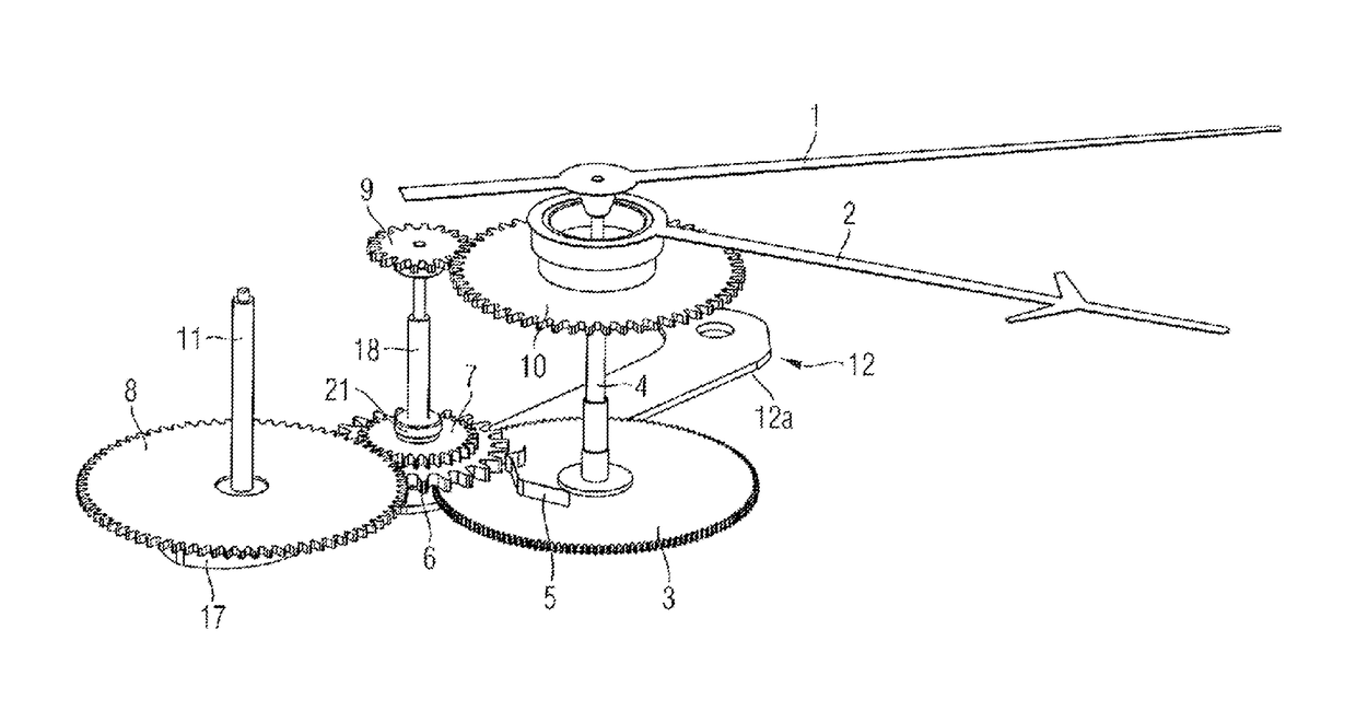
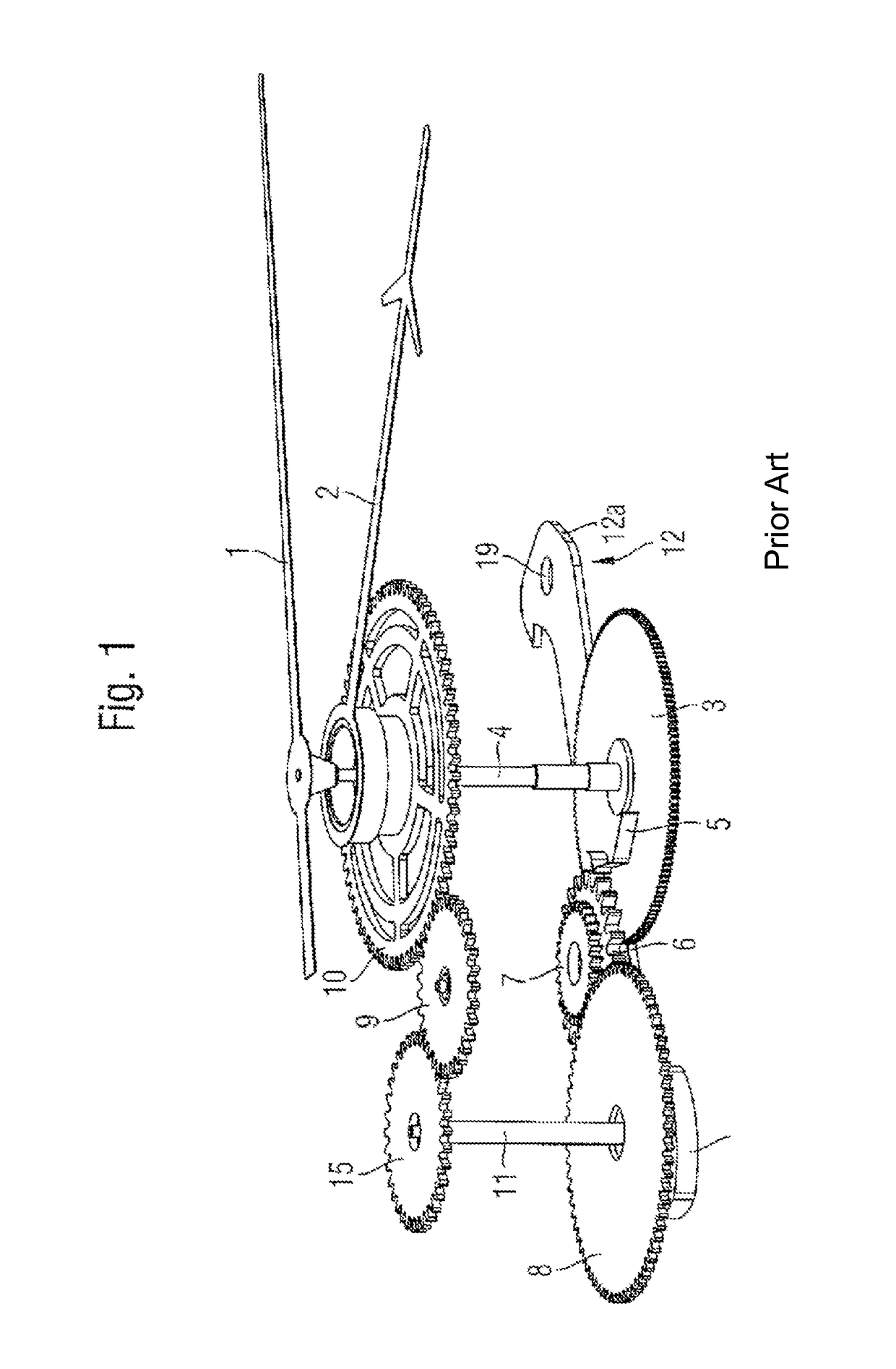
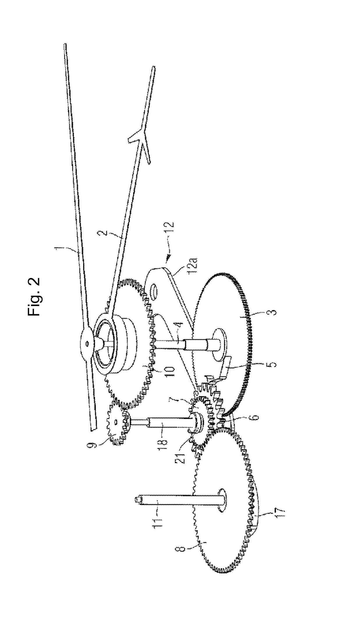
[0022]Due to the inventive use of a multifunction shaft, which is parallel orientated to the second shaft, a drive of the center minute hand is achieved, wherein the drive is associated with reduced friction, compared to the solutions, known from the prior art. In contrast to the four transmissions for transferring the pulse of the entraining spring to the minute wheel, so from the entraining spring to the pulse-receiving wheel, from the drive wheel to the zeroing wheel, from the intermediate wheel to the pulse-transmitting wheel and from the pulse-transmitting wheel to the minute wheel, the solution, according to the invention only requires two transmission, so from the entraining spring to the pulse-receiving wheel and from the pulse-transmitting wheel to the minute wheel. A short, direct way from the entraining spring of the second wheel to the minute wheel is achieved by the multifunction shaft. A reduced frictional loss and an optimal pulse transmission is associated with the reduced number of transmission for transmitting the pulse. This finally results in an increased accuracy of the chronograph.

Problems solved by technology

Without delivering energy permanently, the balance wheel would however stop its movement.

Method used


Image

  • Chronograph
  • Chronograph
  • Chronograph

Examples


Embodiment Construction

[0029]With specific reference now to the drawings in detail, it is stressed that the particulars shown are by way of example and for purposes of illustrative discussion of the preferred embodiments of the present invention only, and are presented in the cause of providing what is believed to be the most useful and readily understood description of the principles and conceptual aspects of the invention. In this regard, no attempt is made to show structural details of the invention in more detail than is necessary for a fundamental understanding of the invention, the description taken with the drawings making apparent to those skilled in the art how the several forms of the invention may be embodied in practice.

[0030]While the present invention is described with respect to what is presently considered to be the preferred aspects, it is to be understood that the invention as claimed is not limited to the disclosed aspect. The present invention is intended to include various modificatio...


PUM


Abstract

A chronograph having a second wheel with an entraining spring, a pulse-receiving wheel, wherein the entraining spring is constructed to engage with the pulse-receiving wheel, a pulse-transferring wheel, a minute wheel, wherein the minute wheel is in constant engagement with the pulse-transferring wheel, a second shaft, wherein the second wheel is rigidly connected to the second shaft, a multifunction shaft is orientated parallel to the second shaft, wherein the pulse-receiving wheel and the pulse-transferring wheel is rigidly connected to the multifunction shaft, and, a two-part constructed zeroing lever having a zeroing lever arm and a zeroing lever interlock, wherein the zeroing lever arm is supported in a rotatable manner around a pivotal point of a zeroing lever arm and the zeroing lever interlock is supported in a rotatable manner around a pivotal point of zeroing lever interlock.

Description

CROSS-REFERENCE TO RELATED APPLICATIONS[0001]This application is filed under 35 U.S.C. § 111(a) and § 365(c) as a continuation of International Patent Application No. PCT / IB2014 / 060166, filed Mar. 26, 2014, which application claims priority from German Patent Application No. DE 10 2013 103 180.3, filed Mar. 28, 2013, which applications are incorporated herein by reference in their entireties.FIELD OF THE INVENTION[0002]The present invention relates generally to a chronograph.BACKGROUND OF THE INVENTION[0003]A mechanic clockwork has as central components a mainspring barrel, a gear train, an escapement and an oscillator (balance wheel). Thereby the barrel with the mainspring provides the drive of the clockwork. Transferring the force occurs beginning at the mainspring barrel, via the movement to the escape wheel, which constitutes a component of the escapement. The movement drives the hands of the clock and transmits the spring force, which is stored in the mainspring, into rotations...

Claims


Application Information

Patent Timeline
Patent Type & Authority Patents(United States)
IPC IPC(8): G04F7/08
CPCG04F7/0814
Inventor HEINZ, UWE
Owner HEINZ UWE
Learn More