Field effect transistor and device thereof

Active Publication Date: 2018-06-19
UNITED MICROELECTRONICS CORP
View PDF9 Cites 0 Cited by
  • Summary
  • Abstract
  • Description
  • Claims
  • Application Information

AI Technical Summary

Benefits of technology

The invention aims to improve semiconductor field effect transistors and devices. Its goal is to fix the problems and flaws of older methods.

Problems solved by technology

However, the critical device size continues to shrink, resulting in a short channel effect.

Method used


Image

  • Field effect transistor and device thereof
  • Field effect transistor and device thereof
  • Field effect transistor and device thereof

Examples


Embodiment Construction

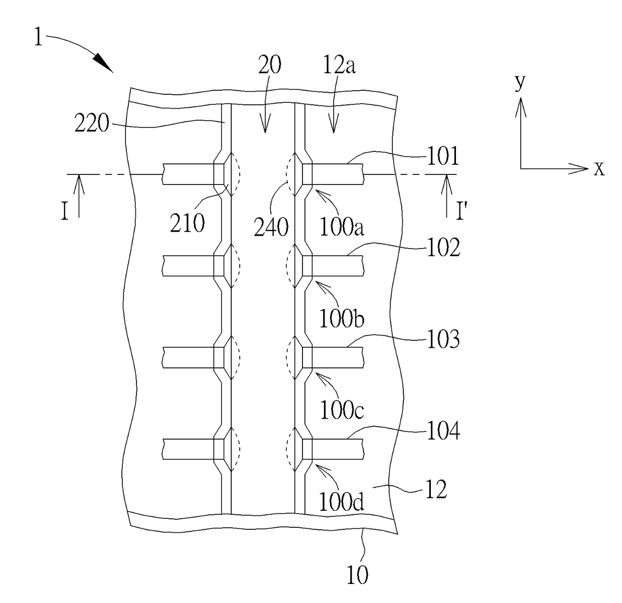
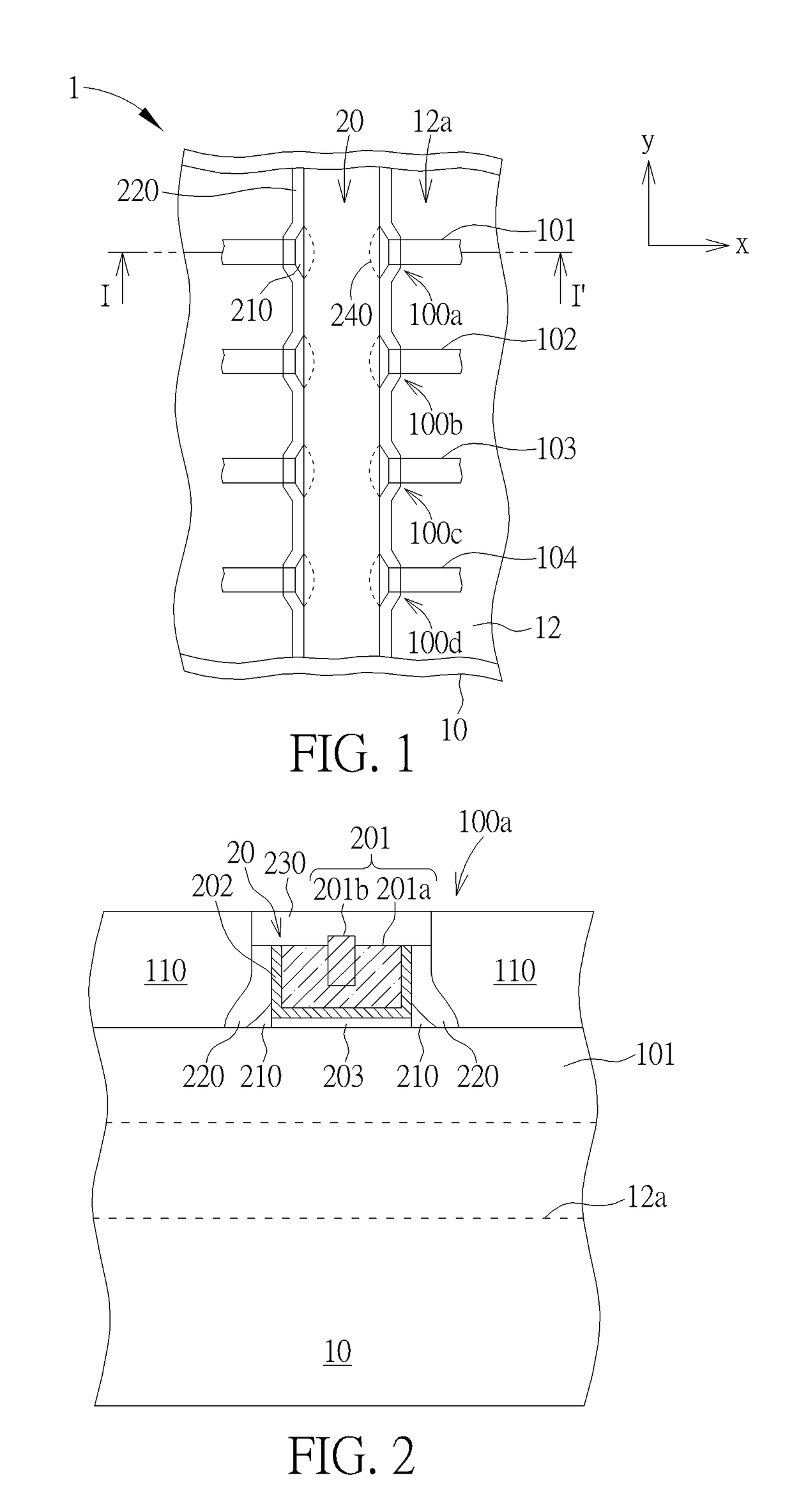
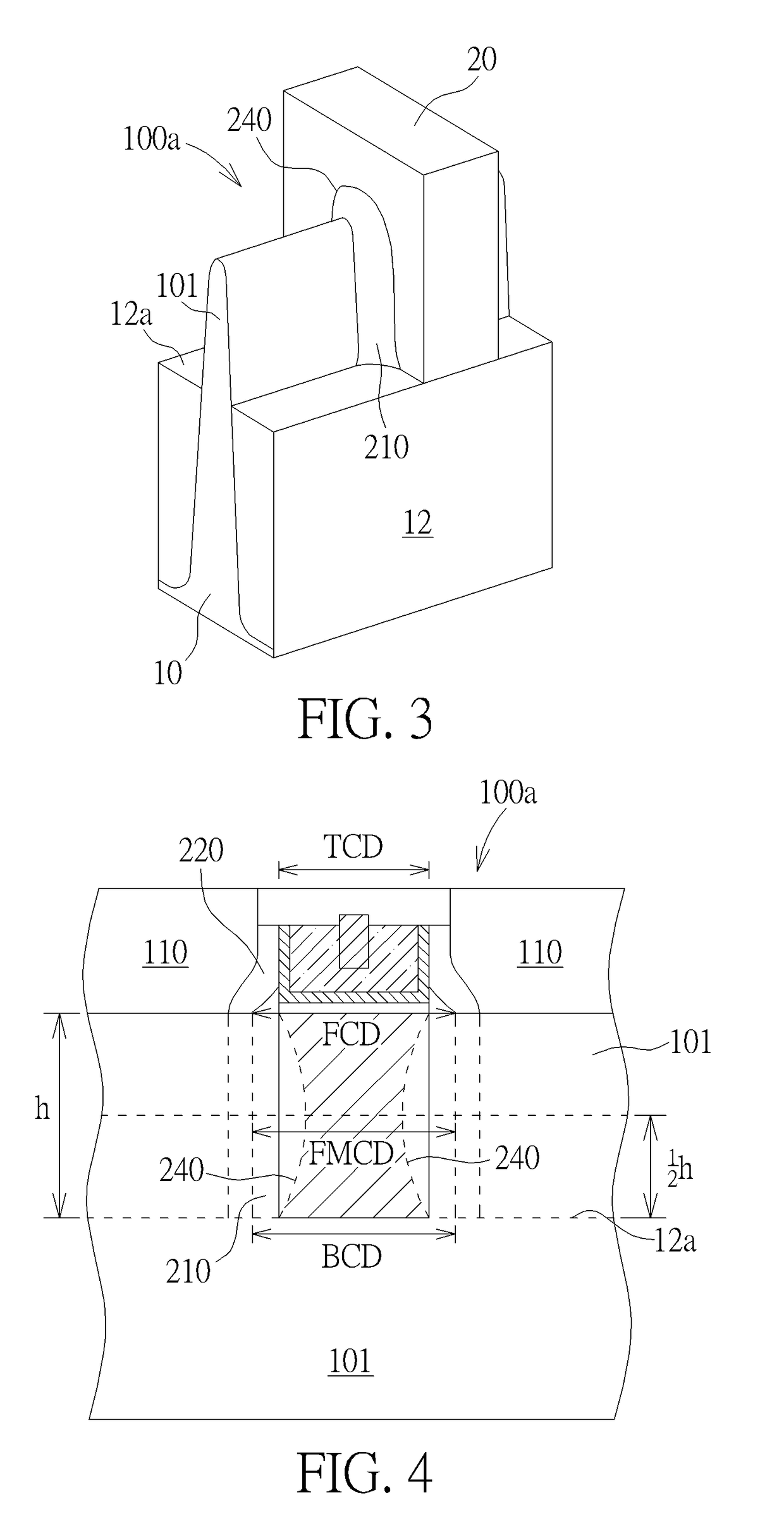
[0014]In the following detailed description of the disclosure, reference is made to the accompanying drawings, which form a part hereof, and in which is shown, by way of illustration, specific embodiments in which the invention may be practiced. These embodiments are described in sufficient detail to enable those skilled in the art to practice the invention. Other embodiments may be utilized and structural changes may be made without departing from the scope of the present disclosure.

[0015]The following detailed description is, therefore, not to be taken in a limiting sense, and the scope of the present invention is defined only by the appended claims, along with the full scope of equivalents to which such claims are entitled. One or more implementations of the present invention will now be described with reference to the attached drawings, wherein like reference numerals are used to refer to like elements throughout, and wherein the illustrated structures are not necessarily drawn ...


PUM


Abstract

A field-effect transistor includes a substrate having thereon an isolation region. A fin structure protrudes from a top surface of the isolation region. The fin structure extends along a first direction. A gate electrode strides across the fin structure and extends along a second direction. A fin corner layer wraps a lower portion of the gate electrode around the fin structure. A spacer covers a sidewall of the gate electrode and the fin corner layer.

Description

CROSS REFERENCE TO RELATED APPLICATION[0001]This application claims priority from Taiwan Patent Application Ser. No. 106121736 filed Jun. 29, 2017, which is included in its entirety herein by reference.BACKGROUND OF THE INVENTION1. Field of the Invention[0002]Embodiments of the present invention relates to the field of semiconductor technology, and in particular to a semiconductor field effect transistor and device.2. Description of the Prior Art[0003]In advanced semiconductor technology, fin-type field effect transistor (FinFET) has replaced the traditional planar-type transistors, and become a mainstream complementary metal oxide semiconductor (CMOS) technology. Typically, at the beginning of the formation of the FinFET, an isolation trench is formed in the semiconductor substrate by at least a patterning process such as lithography and etching to transfer the pattern to the semiconductor substrate, and a plurality of fin structures are defined by the formation of the isolation tr...

Claims


Application Information

Patent Timeline
IPC IPC(8): H01L29/78H01L29/06
CPCH01L29/0653H01L29/7854
Inventor CHANG, I-FANLEE, CHI-JUWU, YEN-LIANGCHANG, WEN-TSUNGYANG, JUI-MINGLU, DIEN-YANG
Owner UNITED MICROELECTRONICS CORP
Why Eureka
Try Eureka