Semiconductor device and fabrication method thereof

a technology of semiconductor devices and semiconductors, applied in the field of semiconductor devices, can solve problems such as affecting the yield of processes

Active Publication Date: 2019-01-01
UNITED MICROELECTRONICS CORP
View PDF1 Cites 2 Cited by
  • Summary
  • Abstract
  • Description
  • Claims
  • Application Information

AI Technical Summary

Benefits of technology

[0005]The main object of the present invention is to provide an improved semiconductor device and a method for fabricating the same, which can solve the disadvantages and shortcomings of the prior art.
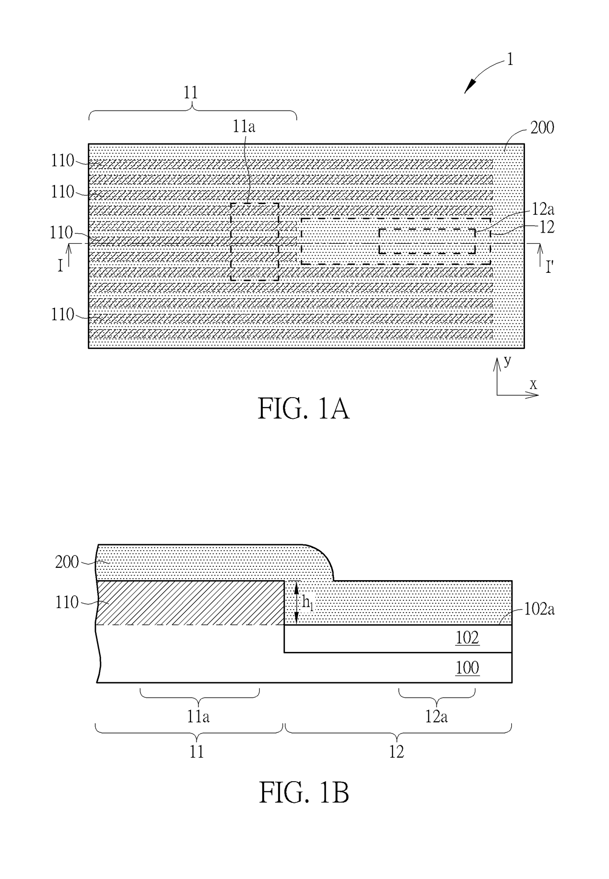
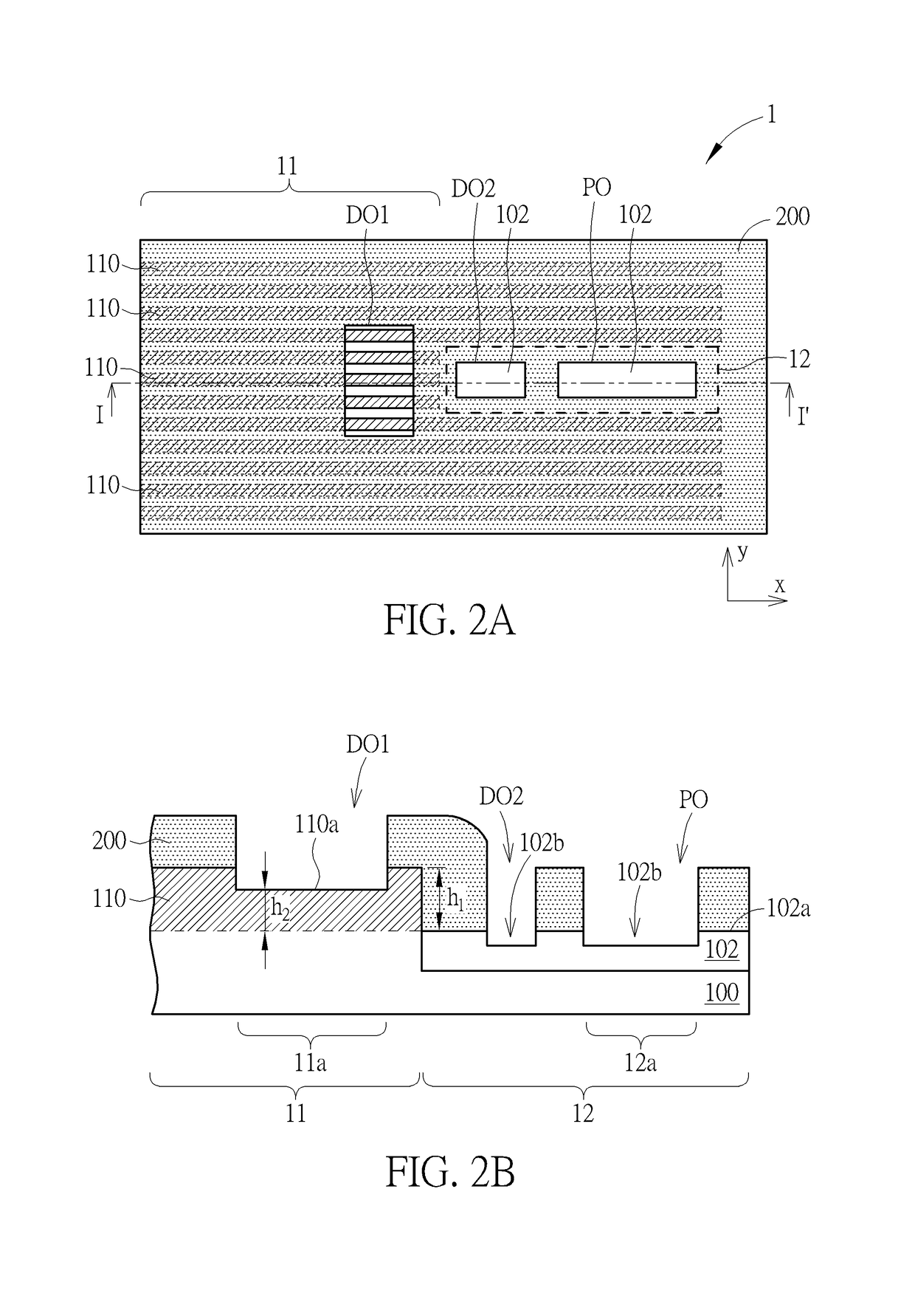
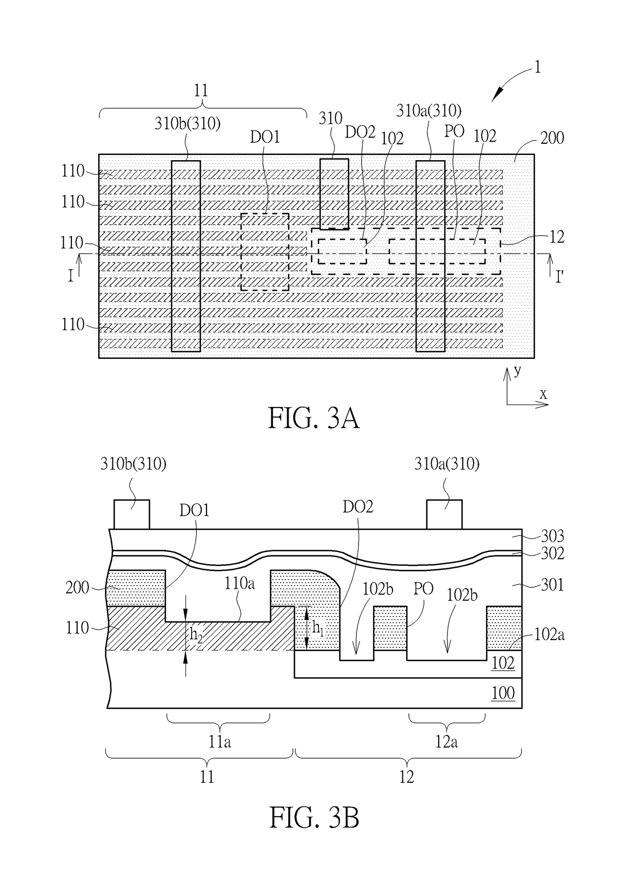
[0006]According to one aspect of the invention, a method for fabricating a semiconductor device is disclosed. A substrate having thereon a trench isolation region and a plurality of fin structures extending along a first direction is provided. The plurality of fin structures protrude from a top surface of the trench isolation region. A polysilicon layer is deposited over the substrate. A poly cut opening and a dummy opening are formed in the polysilicon layer. An organic dielectric layer (ODL) is coated over the substrate. The ODL fills into the poly cut opening and the dummy opening. A hard mask layer is deposited on the ODL. A plurality of photoresist line patterns comprising a first photoresist line pattern and a second photoresist line pattern are formed. The photoresist line patterns extend along a second direction on the hard mask layer. The first photoresist line pattern overlaps with the poly cut opening. The second photoresist line pattern is disposed in proximity to the dummy opening, and does not overlap with the dummy opening. The photoresist line patterns are transferred to the polysilicon layer, thereby forming a plurality of poly lines extending along the second direction.
[0007]According to another aspect of the invention, a semiconductor device includes a substrate having a fin structure extending along a first direction. The fin structure protrudes from a top surface of a trench isolation region and has a first height. A plurality of gate lines including a first gate line and a second gate line extend along a second direction and striding across the fin structure. The first gate line has a discontinuity directly above a gate cut region. The second gate line is disposed in proximity to a dummy fin region, and does not overlap with the dummy fin region. The fin structure has a second height within the dummy fin region, and the second height is smaller than the first height.

Problems solved by technology

However, the prior art slot-cut first process results in a loading effect when coating the organic dielectric layer (ODL), which affects the yield of the process.

Method used


Image

  • Semiconductor device and fabrication method thereof
  • Semiconductor device and fabrication method thereof
  • Semiconductor device and fabrication method thereof

Examples


Embodiment Construction

[0019]In the following detailed description of the disclosure, reference is made to the accompanying drawings, which form a part hereof, and in which is shown, by way of illustration, specific embodiments in which the invention may be practiced. These embodiments are described in sufficient detail to enable those skilled in the art to practice the invention. Other embodiments may be utilized and structural changes may be made without departing from the scope of the present disclosure.

[0020]The following detailed description is, therefore, not to be taken in a limiting sense, and the scope of the present invention is defined only by the appended claims, along with the full scope of equivalents to which such claims are entitled. One or more implementations of the present invention will now be described with reference to the attached drawings, wherein like reference numerals are used to refer to like elements throughout, and wherein the illustrated structures are not necessarily drawn ...


PUM


Abstract

A semiconductor device includes a substrate having a fin structure extending along a first direction. The fin structure protrudes from a top surface of a trench isolation region and has a first height. A plurality of gate lines including a first gate line and a second gate line extend along a second direction and striding across the fin structure. The first gate line has a discontinuity directly above a gate cut region. The second gate line is disposed in proximity to a dummy fin region, and does not overlap with the dummy fin region. The fin structure has a second height within the dummy fin region, and the second height is smaller than the first height.

Description

CROSS REFERENCE TO RELATED APPLICATION[0001]This application claims the benefit of Taiwan patent application No. 106134510, filed on Oct. 6, 2017, the disclosure of which is incorporated herein in its entirety by reference.BACKGROUND OF THE INVENTION1. Field of the Invention[0002]The present invention relates to the field of semiconductor technology, and in particular to a FinFET semiconductor device and a method for fabricating the same.2. Description of the Prior Art[0003]In recent years, due to the miniaturization of various consumer electronic products, the size of the semiconductor devices must be minimized to meet the high degree of integration, high performance, low power consumption and a variety of product requirements. However, with the miniaturization of electronic products, the existing planar field effect transistor (planar FET) has been gradually filed to meet the requirements of the product. Thus, non-planar field-effect transistors such as fin-type field effect trans...

Claims


Application Information

Patent Timeline
Patent Type & Authority Patents(United States)
IPC IPC(8): H01L21/8234H01L29/78H01L27/088H01L29/40H01L29/66
CPCH01L27/0886H01L29/7856H01L29/7855H01L29/785H01L21/823431H01L21/823437H01L21/823481H01L29/401H01L29/66545
Inventor HSU, HSIAO-LINLIOU, EN-CHIUAN
Owner UNITED MICROELECTRONICS CORP
Why Eureka
Try Eureka