Drive control apparatus

a control apparatus and drive technology, applied in the direction of testing/monitoring control systems, positive displacement liquid engines, instruments, etc., can solve the problem of limited operation abnormality detected for the cpu by the monitoring ic, and achieve the effect of preventing operation abnormalities

Active Publication Date: 2018-06-26
FUJI ELECTRIC CO LTD
View PDF67 Cites 3 Cited by
  • Summary
  • Abstract
  • Description
  • Claims
  • Application Information

AI Technical Summary

Benefits of technology

[0012]According to the invention, when the supply of a reset signal from the control processor to the watchdog timer stops, the watchdog timer completes measurement of a target timer time so as to continuously cutoff a supply of the control signal. Therefore, when the operational abnormality of avoiding the control processor from normally operating or the operational abnormality unsolved after resetting the control processor occurs in the control processor, the control target apparatus can be prevented from suffering from a bad influence of the operational abnormality in the control processor and the drive control system can be maintained to be in a safe state.
[0016]According to this mode, in a case where the diagnosis means diagnoses to determine that there is the abnormality in the operation of the control processor, the safe state transition processing means causes the control processor to transfer to the safe state before the watchdog timer outputs the cutoff signal. Therefore, the safety of the control target apparatus can be ensured.
[0018]In this mode, the operation range of the control target apparatus is limited in a case where the operational abnormality of the control processor is diagnosed to exist. Therefore, the safety of the control target apparatus can be ensured.
[0020]According to this mode, after the operational abnormality of the control processor is diagnosed to exist, it is possible to prevent the influence of the operational abnormality in the control processor from effecting on the control target apparatus.
[0022]According to this mode, the driving state of the control target apparatus can be caused to gradually transfer to the safe state along with the passage of time in the case where the abnormality is diagnosed to exist in the operation of the control processor. Therefore, it is possible to prevent the operation of the control target apparatus from being unstable.
[0024]In the preferred mode, the safe state transition processing means sets the control processor to be in a hold state in the case where the diagnosis means diagnoses to determine that the abnormality exists in the operation of the control processor. According to this mode, it is possible to prevent the operational abnormality in the control processor from being conspicuous because the control processor is in the hold state.

Problems solved by technology

However, in this technique disclosed in Patent Document 1, the operational abnormality detected for the CPU by the monitoring IC is limited to specific abnormality such as operational abnormality in a torque monitoring unit and operational abnormality in a signal abnormality diagnosing unit.
Further, the technique disclosed in Patent Document 1 has a problem that a wide range of operational abnormality, which may be caused in the operation of the CPU, such as operational abnormality of arithmetic logic unit (ALU), operational abnormality of a data path, operational abnormality of a register, operational abnormality of an internal RAM, operational abnormality of an address calculation, operational abnormality of interrupt processing, operational abnormality of control logic, and operational abnormality of a configuration register operational abnormality, is not dealt with by detecting this wide range of operational abnormality.
However, if supply of a periodic watchdog timer clear signal is stopped, the watchdog timer determines that the CPU does not normally operate and send an error report to a higher-level system.

Method used


Image

  • Drive control apparatus
  • Drive control apparatus
  • Drive control apparatus

Examples


Embodiment Construction

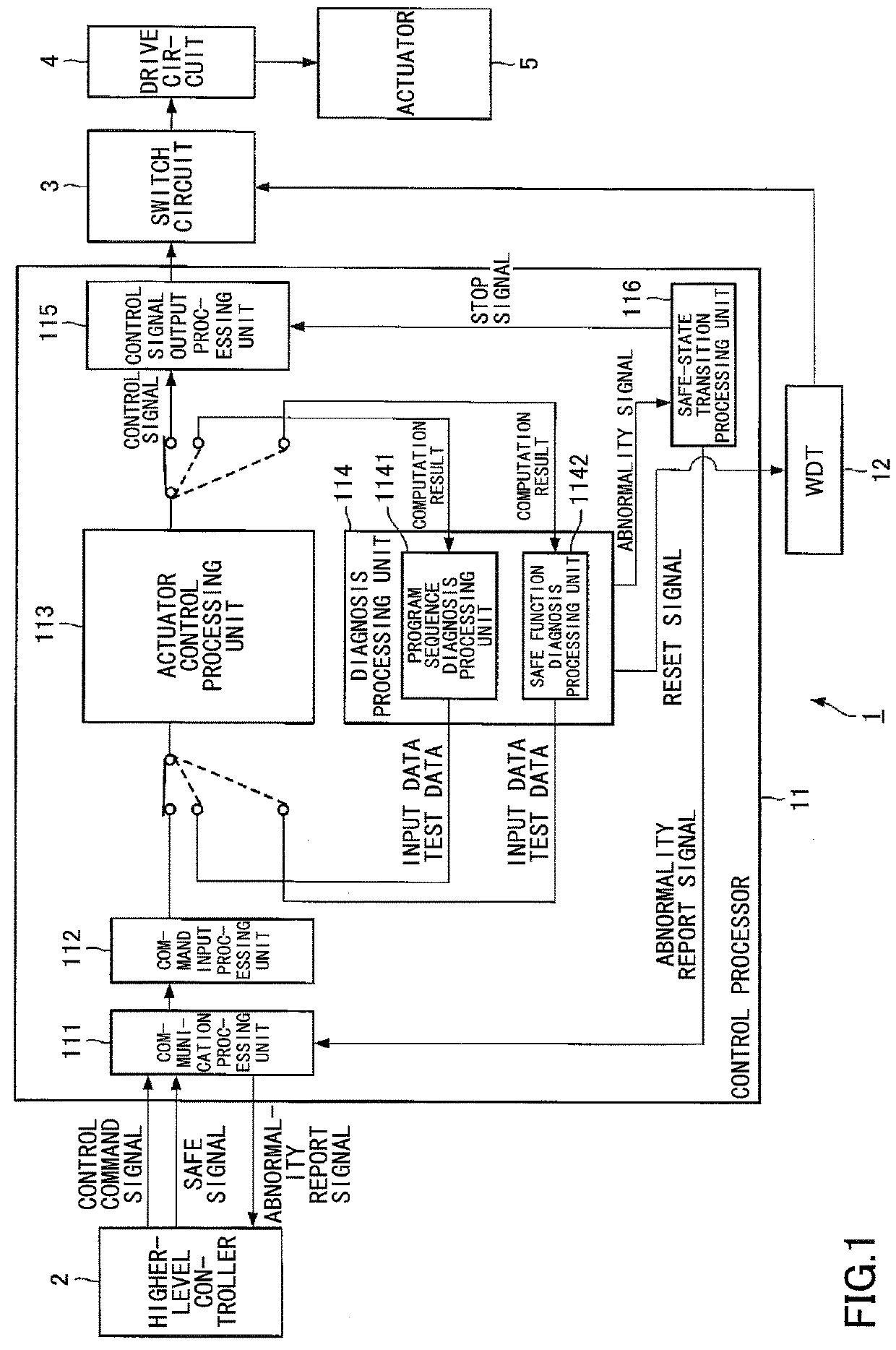
[0032]Here, the technique disclosed in Patent Document 2 has a problem that there is no countermeasure against a case where the reset function of the CPU being a control processor does not normally operate even if a rest signal is given. Further, the technique disclosed in Patent Document 2 has a problem that even if the reset function of the CPU being the control processor normally operates, a normal operation of the CPU is not ensured after resetting the CPU. The technique disclosed in Patent Documents 2 and 3 has a problem that, in a case where the operation of the watchdog timer becomes abnormal, it is difficult to maintain the drive control system to be in a safe state.

[0033]The present invention is provided in consideration of the above described situation. The first object of the invention is to provide a drive control apparatus that can maintain a drive control system to be in a safe state even in a case where operational abnormality of avoiding a control processor from norm...


PUM


Abstract

There is provided a drive control apparatus that can maintain a drive control system to be in a safe state even in a case where operational abnormality of avoiding a normal reset of a control processor or operational abnormality of avoiding solution even after resetting the control processor occurs in the control processor. The control processor includes an actuator control processing unit configured to generate a control signal for a drive circuit being a control target apparatus and an actuator, and a diagnosis processing unit configure to diagnosing the actuator control processing unit. The diagnosis processing unit cyclically outputs a reset signal to WDT in a case where the operation of the control processor is normal. The WDT continuously outputs a cutoff signal for cutting off a supply of the control signal from the control processor to the control target apparatus when the cyclic reset signal stops.

Description

CROSS-REFERENCE TO RELATED APPLICATIONS[0001]This application is a continuation application filed under 35 U.S.C. 111(a) claiming the benefit under 35 U.S.C. 120 and 365(c) of a PCT International Application No. PCT / JP2016 / 055278 filed on Feb. 23, 2016, which is based upon and claims the benefit of priority of the prior Japanese Patent Application No. 2015-089082 filed on Apr. 24, 2015, the entire contents of which are incorporated herein by reference.BACKGROUND OF THE INVENTION[0002]1. Field of the Invention[0003]The present invention relates to a drive control apparatus including a watchdog timer.[0004]2. Description of the Related Art[0005]In a drive control system that performs a drive control of a control target apparatus such as an actuator using a central processing unit (hereinafter, referred to as a CPU), a countermeasure to an abnormality or a failure is positively required. Therefore, various techniques of monitoring the CPU to detect the abnormality or the failure are be...

Claims


Application Information

Patent Timeline
Patent Type & Authority Patents(United States)
IPC IPC(8): G05B9/02F04B49/06G05B23/02
CPCF04B49/065G05B23/0218G05B9/02G05B2219/26G06F11/07G06F11/0757G06F11/0796
Inventor TAJIMA, HIROKAZUNISHIDA, HIROJI
Owner FUJI ELECTRIC CO LTD
Why Eureka
Try Eureka